
Method for calculating deformation of throttle valve disc of hydraulic damper combination valve under action force of spiral spring

A technology of hydraulic shock absorber and coil spring, which is applied in calculation, instrumentation, and special data processing applications, etc. It can solve problems such as reliable design of shock absorber valve system parameters and accurate modeling of characteristic simulation, so as to avoid repeated trials and modification, reduce design cost, improve the effect of development cycle

Inactive Publication Date: 2012-12-26
SHANDONG UNIV OF TECH
View PDF1 Cites 15 Cited by
  • Summary
  • Abstract
  • Description
  • Claims
  • Application Information

AI Technical Summary

Problems solved by technology

Therefore, the current analytical calculation method for the deformation of the valve plate under uniform load cannot meet the requirements of reliable design of the shock absorber valve system parameters and accurate modeling of characteristic simulation, and must also solve the analytical calculation of the deformation of the throttle valve plate under the force of the spring question

Method used


Image

  • Method for calculating deformation of throttle valve disc of hydraulic damper combination valve under action force of spiral spring
  • Method for calculating deformation of throttle valve disc of hydraulic damper combination valve under action force of spiral spring
  • Method for calculating deformation of throttle valve disc of hydraulic damper combination valve under action force of spiral spring

Examples


Embodiment Construction

[0021] The present invention will be further described in detail through an embodiment below.

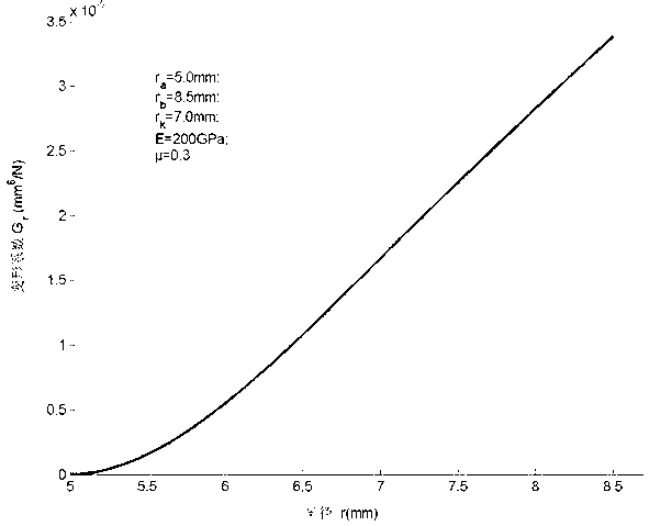
[0022] For example, the inner radius of an annular throttle plate r a =5.0mm, outer radius r b =8.5mm, valve thickness h =0.3mm, coil spring preload F 0 =5N, loading radius r k =7mm, take the preload F 0 The width of the microcircle to act on mm, that is r t = 7.1 mm.

[0023] The specific steps of the method for calculating the deformation of the throttle plate of the cylindrical hydraulic shock absorber under the force of the spring provided by the embodiment of the present invention are as follows.

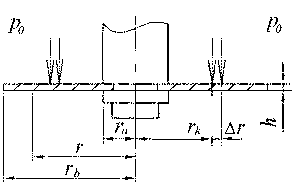
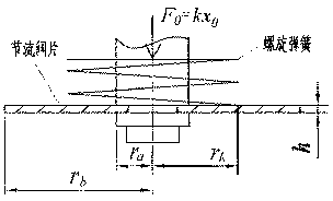
[0024] (1) According to the physical model of the throttle plate of the shock absorber under the spring preload, such as figure 2 As shown, the equivalent simplified mechanical model of the throttle valve plate is established, such as image 3 Shown; the middle of the annular elastic throttle valve plate is a fixed constraint, and the effective inner circle radius is...


PUM


Abstract

The invention relates to a method for calculating deformation of a throttle valve disc of hydraulic damper combination valve under the action force of a spiral spring, which belongs to the field of dampers; the invention aims at solving the problem of calculating the deformation that restricts the analytical design of practical dampers and the characteristic stimulation modelling valve discs. The method provided by the invention comprises the steps of establishing an equivalent simplified mechanical model of the throttle valve disc according to the physical model of the damper throttle valve disc under the action of spring force; establishing the bending deformation curved surface differential equation of the throttle valve disc under the spring action force by utilizing the theory of the elasticity mechanics; obtaining the general solution of the differential equation by utilising the boundary constraint condition of the throttle valve disc and the continuous condition at the loading position; and establishing the bending deformation coefficient and the bending deformation analytical calculation formula of the throttle valve disc at any radius through the identical transformation. The method provided by the invention avoids the repeated test and modification when designing the damper, reduces the design cost of the damper and improves the development period of the damper; the method provided by the invention can be used for analytic design and characteristic stimulation of the cylinder hydraulic damper.

Description

technical field [0001] The invention relates to a shock absorber, in particular to a method for calculating the deformation of a throttle plate of a hydraulic cylinder type shock absorber under the pre-tightening force of a coil spring. Background technique [0002] The most widely used automobile shock absorber is the cylinder hydraulic shock absorber. Its damping characteristics are mainly determined by the parameters of the shock absorber valve system. Among them, the thickness of the throttle valve plate and its deformation under the force of the spring have a great device characteristics play a key role. At present, there is no accurate and reliable design method for the design of shock absorber valve system parameters at home and abroad. Most of them use experience to first determine a valve plate thickness, and then after repeated tests and modifications, finally determine the design parameters. The main reason is At present, there is a lack of reliable shock absorbe...

Claims


Application Information

Patent Timeline
IPC IPC(8): G06F17/50
Inventor 周长城李红艳赵雷雷
Owner SHANDONG UNIV OF TECH
Learn More