
System and method for debugging FPGA (field programmable gate array) in real time

A technology of data, transceiver module, applied in the field of real-time debugging of FPGA through SPI interface, can solve the problems of inability to realize configuration and debugging, limited, unable to meet the requirements of debugging speed, etc.

Inactive Publication Date: 2012-12-26
BEIJING UPTOPS DESIGN TECH
View PDF5 Cites 8 Cited by
  • Summary
  • Abstract
  • Description
  • Claims
  • Application Information

AI Technical Summary

Problems solved by technology

However, only relying on JTAG to transmit the captured data to the PC can no longer meet the debugging speed requirements of complex systems. In multiple FPGA systems, limited by the JTAG protocol, full-duplex configuration and debugging cannot be realized.

Method used


Image

  • System and method for debugging FPGA (field programmable gate array) in real time
  • System and method for debugging FPGA (field programmable gate array) in real time

Examples


Embodiment Construction

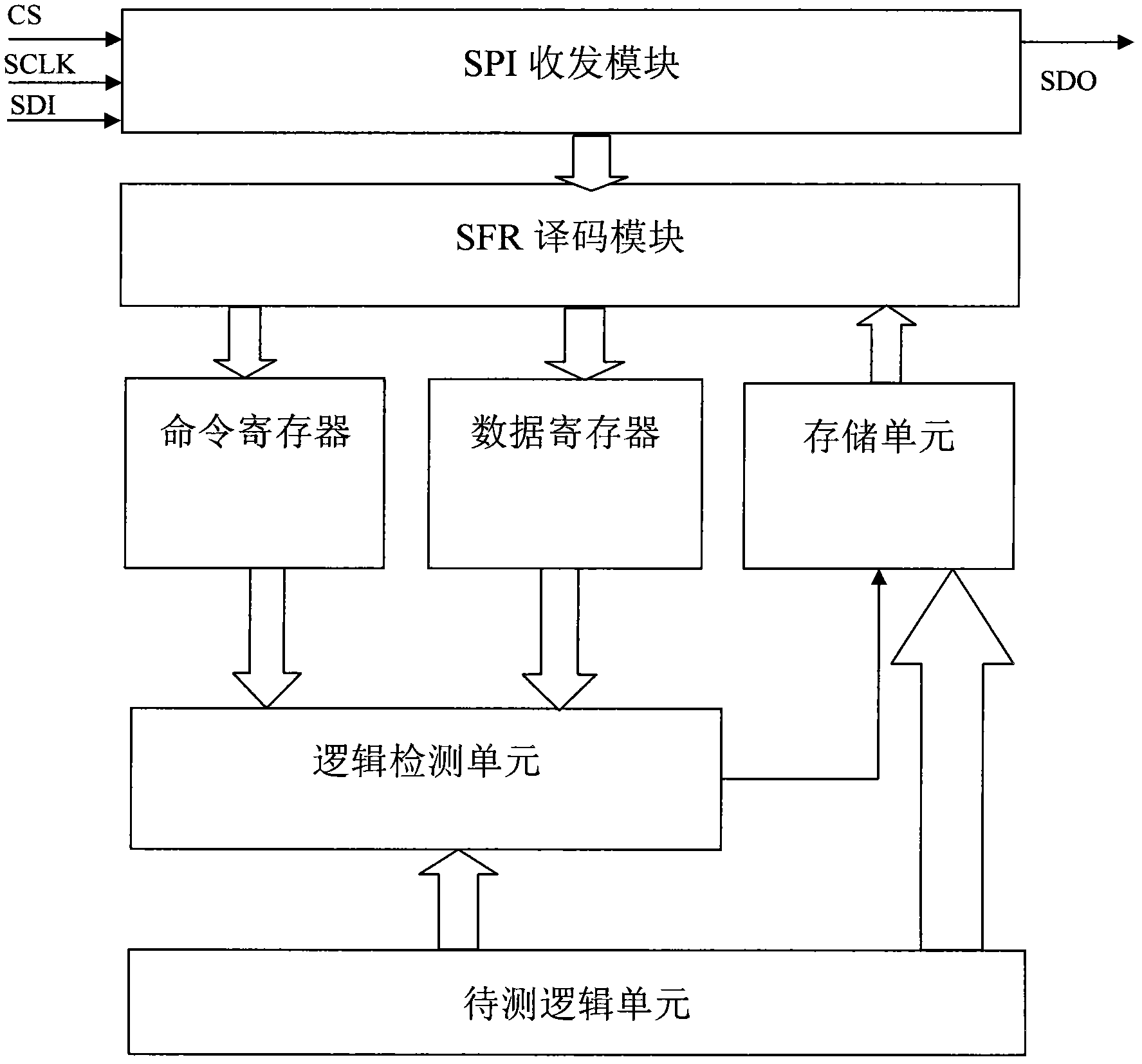
[0024] In order to facilitate the understanding of the technical solutions of the present invention, the following will be introduced in combination with specific implementation manners. Such as figure 1 It is a system structure diagram of FPGA real-time debugging. As shown in the figure, the system includes an SPI transceiver module, which is used to receive external data to form detection commands and detection data, and send internal detection results and internal storage data. The received signal is SDI. Master device data input, slave device data output; SCLK, clock signal generated by the master device; CS, master device controls the enable signal of the slave device; the signal sent is SDO, master device data output, slave device data input; SFR translation The code module is used to decode the register commands of special functions; the data storage unit is used to save the specified sampling data. In this embodiment, the unit is composed of a command register, a data ...


PUM


Abstract

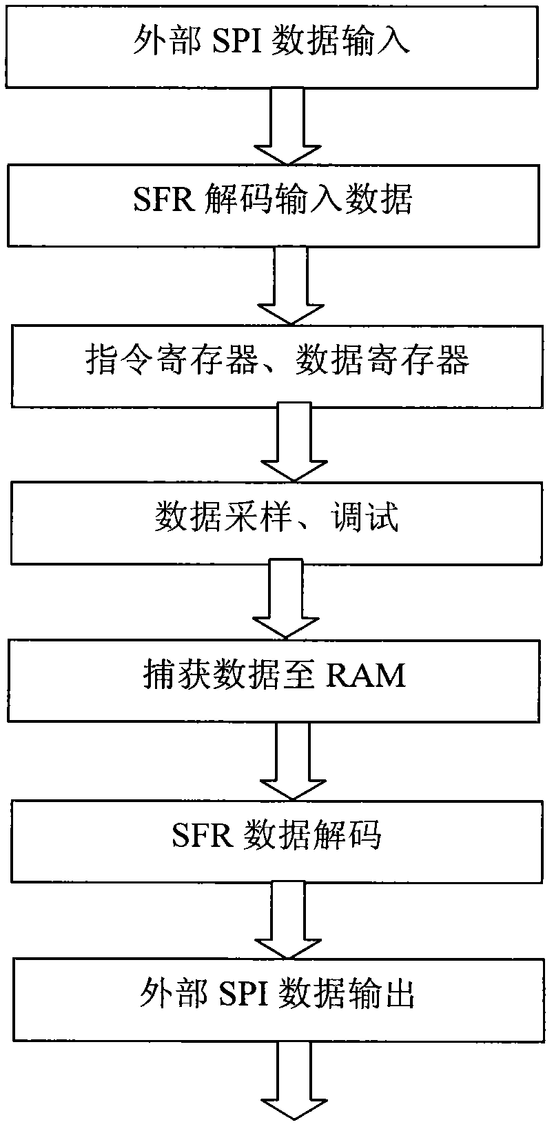
The invention discloses a system for debugging FPGA (field programmable gate array) in real time, comprising an SPI (serial peripheral interface) transceiving module, an SFR (special function register) decoding module, a data storing unit and a logic detection unit, wherein the SPI transceiving module is used for receiving external data to form a detection command and detection data and sending an internal detection result and internal storage data; the SFR decoding module is used for decoding a register command with special functions; the data storing unit is used for storing specified sampled data; and the logic detection unit is used for being connected with at least one group of logic units to be detected and carrying out real-time verification to obtain a verification result; and the modules and the units are sequentially connected for carrying out data communication. A real-time debugging method of the system comprises the following steps that: the SPI transceiving module receives data of a monitoring system, the data received by the SPI transceiving module is converted into a detection instruction or detection data by virtue of the SFR module, is stored by the data storing unit and then is sent to the logic detection unit, the logic detection unit judges the logic units to be detected, and judgement data and result are stored and then are transmitted by the SPI transceiving module. The system disclosed by the invention takes an SPI bus protocol as a protocol used for realizing data interaction between a basic debugging device and equipment, and high-speed product debugging and verifying design and dynamic check debugging are realized.

Description

technical field [0001] The invention relates to the technical field of real-time debugging and dynamic verification of FPGA design, and specifically belongs to a system and method for real-time debugging of FPGA through an SPI (Serial Peripheral Interface) interface to realize the purpose of design verification. Background technique [0002] FPGA (Field-Programmable Gate Array), that is, Field Programmable Gate Array, is a product of further development on the basis of programmable devices such as PAL, GAL, and CPLD. It emerged as a semi-custom circuit in the field of application-specific integrated circuits (ASIC), which not only solves the shortcomings of custom circuits, but also overcomes the shortcomings of the limited number of original programmable device gates. [0003] FPGA adopts the concept of logic cell array LCA (Logic Cell Array), which includes three parts: configurable logic module CLB (Configurable Logic Block), input and input module IOB (Input Output Block...

Claims


Application Information

Patent Timeline
Patent Type & Authority Applications(China)
IPC IPC(8): G01R31/317G01R31/3177
Inventor 朱旭杨龙张东晓
Owner BEIJING UPTOPS DESIGN TECH
Learn More