
Vibration sensor of three-component fiber grating

A vibration sensor, fiber grating technology, applied in instruments, measuring devices, measuring ultrasonic/sonic/infrasonic waves, etc., can solve the problems of easy distortion of spectral signals, low measurement frequency of fiber grating sensors, etc., to widen the measurement frequency range and improve stability. The effect of preventing over-range damage

Active Publication Date: 2012-12-26
SUZHOU NANZEE SENSING TECH
View PDF6 Cites 11 Cited by
  • Summary
  • Abstract
  • Description
  • Claims
  • Application Information

AI Technical Summary

Problems solved by technology

At present, most fiber grating vibration sensors are unidirectional sensors, and most of them stick the fiber grating on a mechanical structure, and rely on the vibration of the mechanical structure to drive the deformation of the fiber grating, but the natural frequency of the sensor depends on the natural frequency of the mechanical structure. Therefore, the current fiber grating sensor has a low measurement frequency, and the spectral signal is easily distorted

Method used


Image

  • Vibration sensor of three-component fiber grating
  • Vibration sensor of three-component fiber grating
  • Vibration sensor of three-component fiber grating

Examples


Embodiment

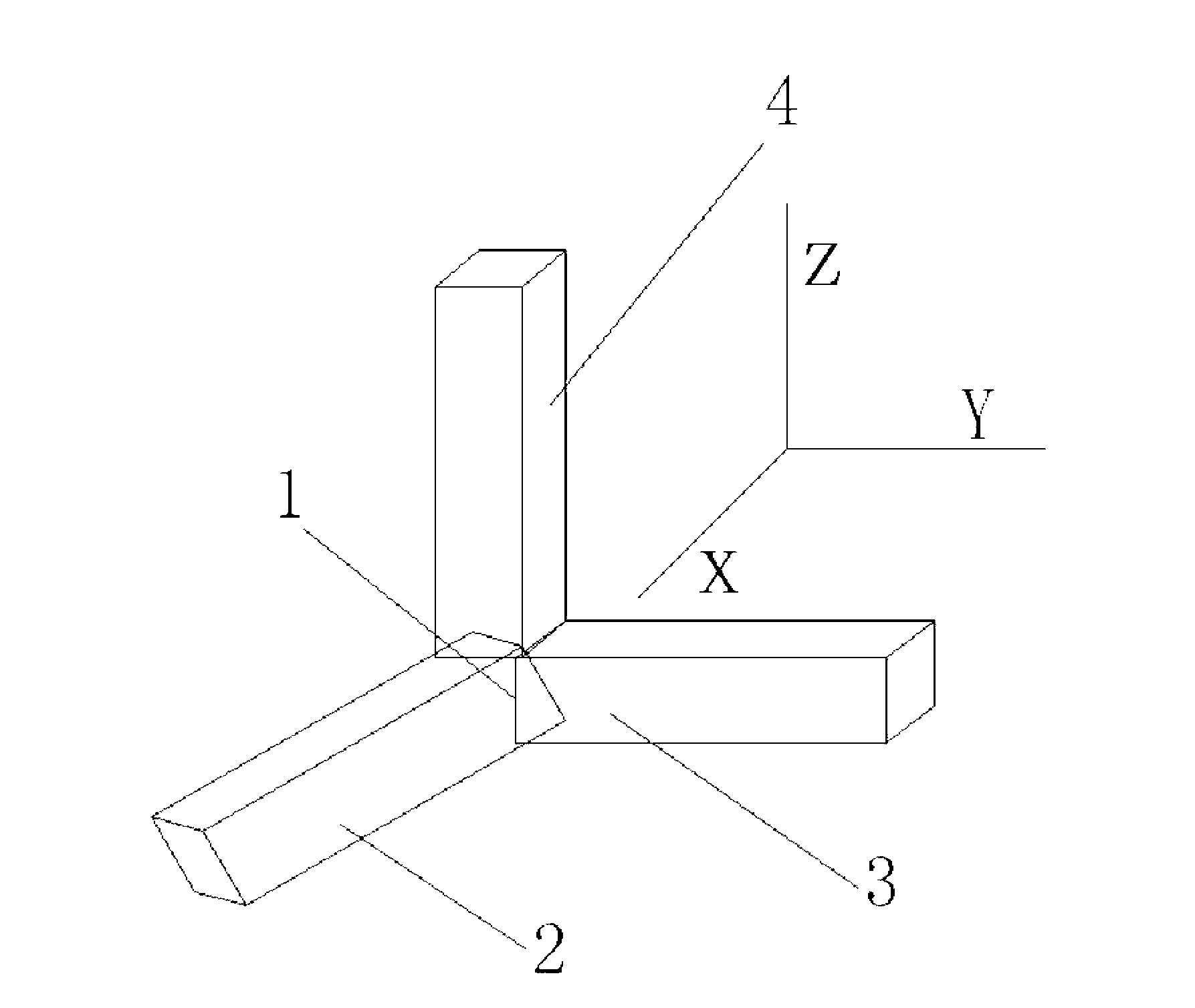
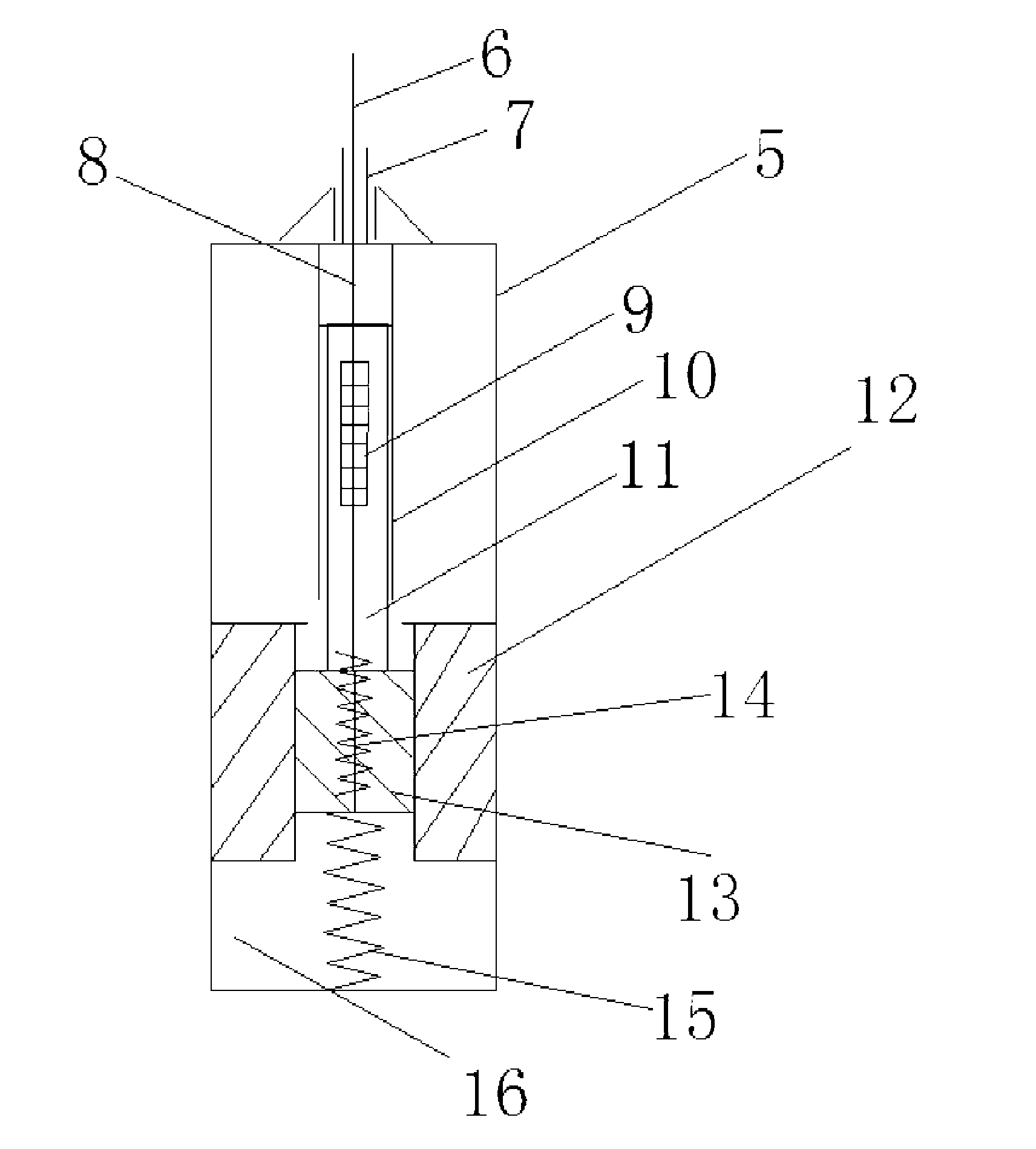
[0028] Example: such as figure 1 As shown, the X-direction sensor 2 , the Y-direction sensor 3 and the Z-direction sensor 4 are all rectangular parallelepiped, with screws at the top, which are fixed on the base 1 through threads perpendicular to each other. The sensor housing 5 is composed of two parts, the main body is a groove-like structure, the main structure of the sensor is placed inside, and the other part is a sliding cover. After the sensor is made, the sliding cover and the groove-like structure are bonded together. Such as figure 2 As shown, there is a stainless steel cylinder 10 inside the sensor housing 5 , and the inner wall of the stainless steel cylinder 10 is not in contact with the elastic material 11 coated on the outside of the fiber grating 9 . There is a round hole at the top of the housing 5 through which the transmission optical fiber 6 and the sleeve 7 pass through, and the colloid 8 bonds the transmission optical fiber 6 and the stainless steel...


PUM


Abstract

The invention discloses a vibration sensor of a three-component fiber grating. The vibration sensor of the three-component fiber grating comprises a base, an outer shell, a fiber grating, an oscillator, an oscillator clamping seat, springs, and the like. Three same vibration sensors are mutually perpendicularly fixed on the base of a sensor. The outer shell of the sensor comprises two parts, the body part of the outer shell of the sensor is a box structure, five surfaces of the box structure are closed, an opening is arranged on one surface of the box structure, and the other part of the outer shell of the sensor is a sliding cover which covers the opening of the box structure. A circular hole is arranged at the top end of the outer shell, and transmission optical fibers and a sleeve pipe penetrate through the circular hole. A stainless steel cylinder is arranged inside the outer shell, the fiber grating which is coated with elastic materials is arranged inside the stainless steel cylinder, the lower end of the fiber grating is connected with the oscillator, the oscillator is arranged inside the oscillator clamping seat, and the lower end of the oscillator is connected with the bottom end of the outer shell of the sensor through a second spring. A grating is not required to be pasted on a mechanical structure so that restriction on natural frequency of the mechanical structure is effectively avoided and range of measuring frequency of the sensor is largely broadened. The vibration sensor of the three-component fiber grating is capable of measuring vibration amplitude, frequency and accelerated speed which are mutually perpendicular in three directions in real time, and preventing effectively over range damage of the sensor.

Description

technical field [0001] The invention relates to a three-component optical fiber grating vibration sensor, in particular to a high-precision optical fiber grating vibration sensor capable of simultaneously measuring vibration signals in three directions of X, Y, and Z. Background technique [0002] Vibration is a ubiquitous phenomenon in nature, and vibration signals need to be detected in fields such as structural engineering, mechanical equipment, aviation and mining. At present, electrical vibration sensors are usually used, but they are easily affected by external factors, especially in harsh environments such as strong electromagnetic interference, high temperature and humidity, high voltage, high current, and loud noise. Traditional vibration sensors are difficult Effectively measure, not even work. [0003] Fiber Bragg grating is an emerging basic optical fiber device in the world since the 1990s. It is used in the field of sensing with good durability, anti-elec...

Claims


Application Information

Patent Timeline
IPC IPC(8): G01H9/00
Inventor 王静魏广庆施斌严珺凡
Owner SUZHOU NANZEE SENSING TECH
Learn More