
Mould-assembling mechanism for injection molding machine and balancing and adjusting method for mould-assembling force thereof

A mold clamping mechanism and injection molding machine technology, which is applied in the field of injection molding machines, can solve problems such as mechanical loss, poor parallelism, and tie rod breakage, and achieve the effects of improved service life, long service life, and high reliability

Active Publication Date: 2012-12-26
TEDERIC MACHINERY
View PDF3 Cites 23 Cited by
  • Summary
  • Abstract
  • Description
  • Claims
  • Application Information

AI Technical Summary

Problems solved by technology

However, the mold clamping mechanism of the prior art may cause the following problems due to mechanical wear or other reasons: 1. The mold clamping force changes, deviates from the optimum set value, and if it becomes smaller, the mold clamping force is insufficient during injection, which will cause The product has peaks; if it becomes larger, unnecessary energy waste, mechanical loss, or failure to close the mold will cause the machine to stop
2. An injection molding machine often replaces different molds according to production needs, and the states of these molds are not the same. If the parallelism of the two mounting surfaces of some molds is poor, after being installed on the injection molding machine, four Uneven tension on the tie rods caused the most stressed tie rod to break and stop production

Method used


Image

  • Mould-assembling mechanism for injection molding machine and balancing and adjusting method for mould-assembling force thereof
  • Mould-assembling mechanism for injection molding machine and balancing and adjusting method for mould-assembling force thereof
  • Mould-assembling mechanism for injection molding machine and balancing and adjusting method for mould-assembling force thereof

Examples


Embodiment Construction

[0023] The present invention will be further described below in conjunction with the accompanying drawings and specific embodiments.

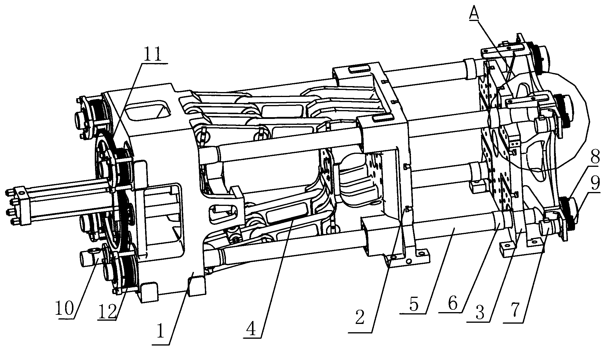
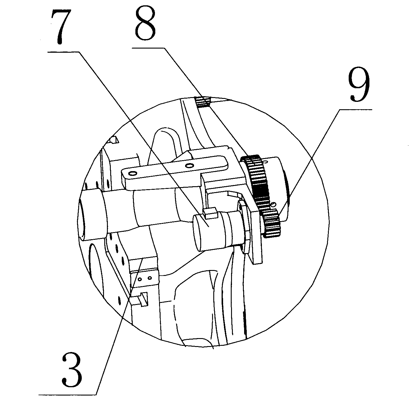
[0024] Such as figure 1 As shown, the injection molding machine clamping mechanism of the present invention includes a rear template 1, a movable template 2, a front template 3, a toggle mechanism 4 and four pull rods 5, and the four pull rods 5 penetrate the rear template 1, the movable template 2 and the front template 3, the rear template 1 and the front template 3 are fixed on the two ends of the pull rod 5, the rear template 1 and the movable template 2 are connected by a toggle mechanism 4; the mold clamping mechanism also includes a pull rod adjustment mechanism, The pull rod adjustment mechanism includes strain gauges 6, servo motors 7 and front nuts 8 corresponding to the four pull rods 5. The positions and directions of the strain gauges 6 on the four pull rods 5 are consistent. The outer peripheral surface of the front nut 8 is gear...


PUM


Abstract

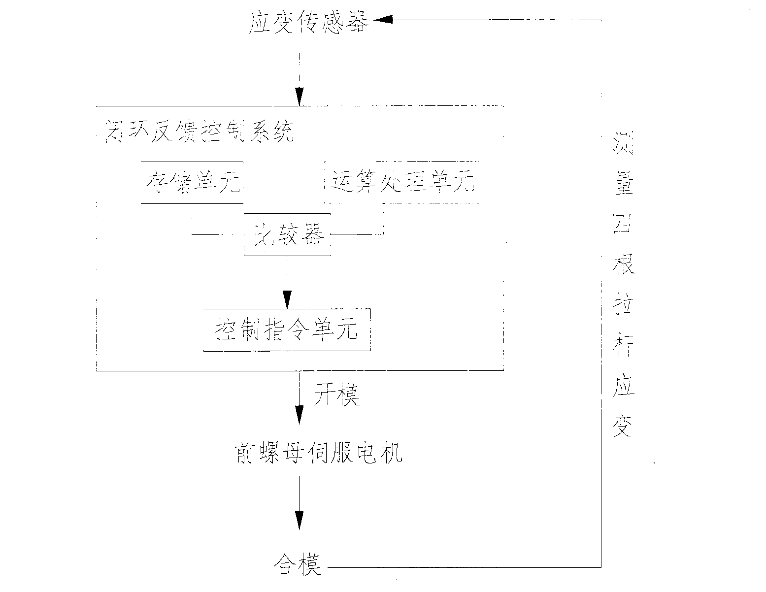
The invention discloses a mould-assembling mechanism for an injection molding machine and a balancing and adjusting method for a mould-assembling force thereof. The mould-assembling mechanism comprises a rear mould plate (1), a moveable mould plate (2), a front mould plate (3), a toggle rod mechanism (4), four pull rods (5) and a pull rod adjusting mechanism, wherein the pull rod adjusting mechanism comprises strain foils (6), servo motors (7) and front nuts (8) which are one-to-one corresponding to the four pull rods (5); the positions and directions of the strain foils (6) on the four pull rods (5) are consistent; the peripheral surfaces of the front nuts (8) are gear-shaped; driving gears (9) are connected with the servo motors (7); and the driving gears (9) are engaged with the peripheral surfaces of the front nuts (8). The uniform stress of the four pull rods is realized by adopting a closed-loop feedback control balancing and adjusting method, so that the function of balancing and adjusting the mould-assembling force is achieved, the reliability of the mould-assembling mechanism is high and the service life is long.

Description

technical field [0001] The invention relates to the field of injection molding machines, in particular to a mold clamping mechanism of an injection molding machine and a method for adjusting the balance of mold clamping force. Background technique [0002] The mold clamping mechanism is the main part of the plastic injection molding machine. At present, the common mold clamping mechanisms include connecting rod type, full hydraulic type, two-plate type and no tie rod type. Except for the tie-bar-free type, the mold clamping structures of the other three plastic injection molding machines all need tie rods as force balance elements. For example, the mold clamping mechanism of the toggle-type injection molding machine, the four pull rods are covered with the rear template, the movable template and the front template, the movable template and the rear template are connected by the toggle mechanism, and the rear nut is provided at the connection between the rear template and the...

Claims


Application Information

Patent Timeline
IPC IPC(8): B29C45/68B29C45/76
Inventor 吴敬阳
Owner TEDERIC MACHINERY
Learn More