
Fuse for motor vehicle power line

A technology for safety devices and power lines, which is applied to circuits, electric switches, and electrical components, and can solve problems such as high material investment, high cost, and high cost of safety switches

Active Publication Date: 2012-12-19
AUTO KABEL MANAGEMENTGMBH
View PDF16 Cites 6 Cited by
  • Summary
  • Abstract
  • Description
  • Claims
  • Application Information

AI Technical Summary

Problems solved by technology

[0006] All of the above electronic cutouts are expensive to manufacture
In addition, the material investment is high, so this type of safety switch is expensive

Method used


Image

  • Fuse for motor vehicle power line
  • Fuse for motor vehicle power line
  • Fuse for motor vehicle power line

Examples


Embodiment Construction

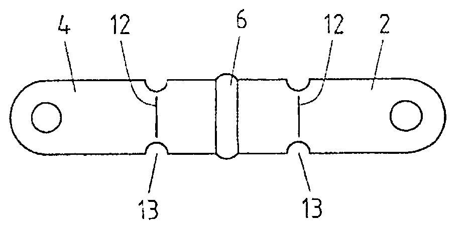
[0032] figure 1 Two webs 2 , 4 formed as planar parts are shown. The connecting pieces 2, 4 are at a distance from each other so that a connecting part 6, in the case of the figure soft solder, can be arranged in the gap 18 between the connecting pieces 2, 4. The connecting part 6 connects the connecting pieces 2, 4 both electrically and mechanically.

[0033] It can be seen that the webs 2 , 4 close the ballistic path 8 of the housing 14 of the ignition device 10 .

[0034] The housing 14 here is made of plastic and the housing walls are strong enough to withstand the gas pressure of the activated igniter 10 . It can be seen that the kindling 10 can be ignited by the electronic ignition wire. The ignition pulses can be received, for example, by an airbag control unit.

[0035] The connecting pieces 2 , 4 are bonded to the casing 14 in such a way that the ballistic 8 is sealed such that the gas pressure generated when the ignition charge 10 is triggered is sufficient to se...


PUM


Abstract

A current interrupter for motor-vehicle power lines having a first flat connecting lug, a second connecting lug and a connection part which electrically connects the connecting lugs and forms a weak point. Particularly simple production with little use of material can be achieved by the connecting lugs and the electrical connection part closing an explosion chamber of a pyrotechnic fuze such that the gas pressure which acts on initiation of the pyrotechnic fuze bursts the weak point.

Description

technical field [0001] The invention relates to a current circuit breaker for a vehicle power line, in particular comprising a connecting piece [0002] Formed connection parts that can be disconnected by pyrotechnics. Background technique [0003] Pyrotechnic insurance is well known in the field of automotive technology. An electronic safety switch which can be activated pyrotechnically is known, inter alia, from European patent application EP 0 665 556 A1. The safety switch is actuated in such a way that the propellant acts on a movable contact part which, by its movement, is carried away from the other contact part, thereby breaking the electrical path. In this method, there is always a piston driven in the sheath. The piston is driven by a pyrotechnic propellant in the sheath. Said safety switch is expensive to produce and is therefore expensive to manufacture. [0004] An electronic safety switch is likewise known from the German utility model DE 203 17 189 U1, whi...

Claims


Application Information

Patent Timeline
Patent Type & Authority Applications(China)
IPC IPC(8): H01H39/00
CPCH01H2039/008H01H39/006
Inventor 沃尔夫冈・亨舍尔
Owner AUTO KABEL MANAGEMENTGMBH
Learn More