Ion source and ion implantation apparatus

An ion implantation device and ion source technology, which is applied in the direction of ion beam tubes, discharge tubes, electrical components, etc., can solve the problems of device operation rate deterioration, filament consumption, filament heating, etc., to achieve less disconnection and reduce sputtering , the effect of stabilizing large and high current

Inactive Publication Date: 2012-12-19
NISSIN ION EQUIP CO LTD
View PDF6 Cites 8 Cited by
  • Summary
  • Abstract
  • Description
  • Claims
  • Application Information

AI Technical Summary

Problems solved by technology

However, since the increase of the amount of electron emission means that the amount of current flowing through the filament increases, the filament is heated to a higher temperature, so the evaporation of the filament due to heating progresses further, resulting in thinning of the filament
[0009] In the ion source of Patent Document 1, if the amount of current flowing through the filament is increased to increase the beam current of the ion beam, due to the above-mentioned sputtering effect on the filament caused by the plasma and the high temperature of the filament The superposition of the evaporation effect, there is a problem that the filament will be consumed in a very short time
If the filament breaks due to filament consumption, the ion source must be stopped for maintenance, so the operating rate of the device deteriorates

Method used


Image

  • Ion source and ion implantation apparatus
  • Ion source and ion implantation apparatus
  • Ion source and ion implantation apparatus

Examples


Embodiment Construction

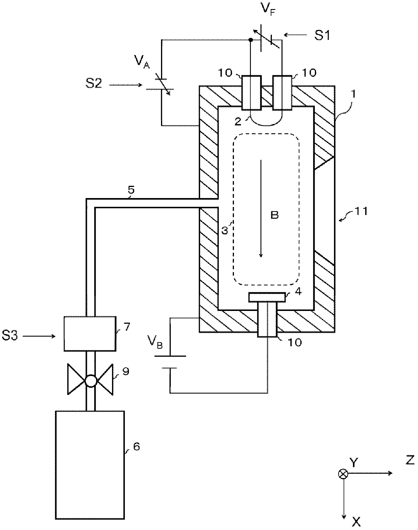
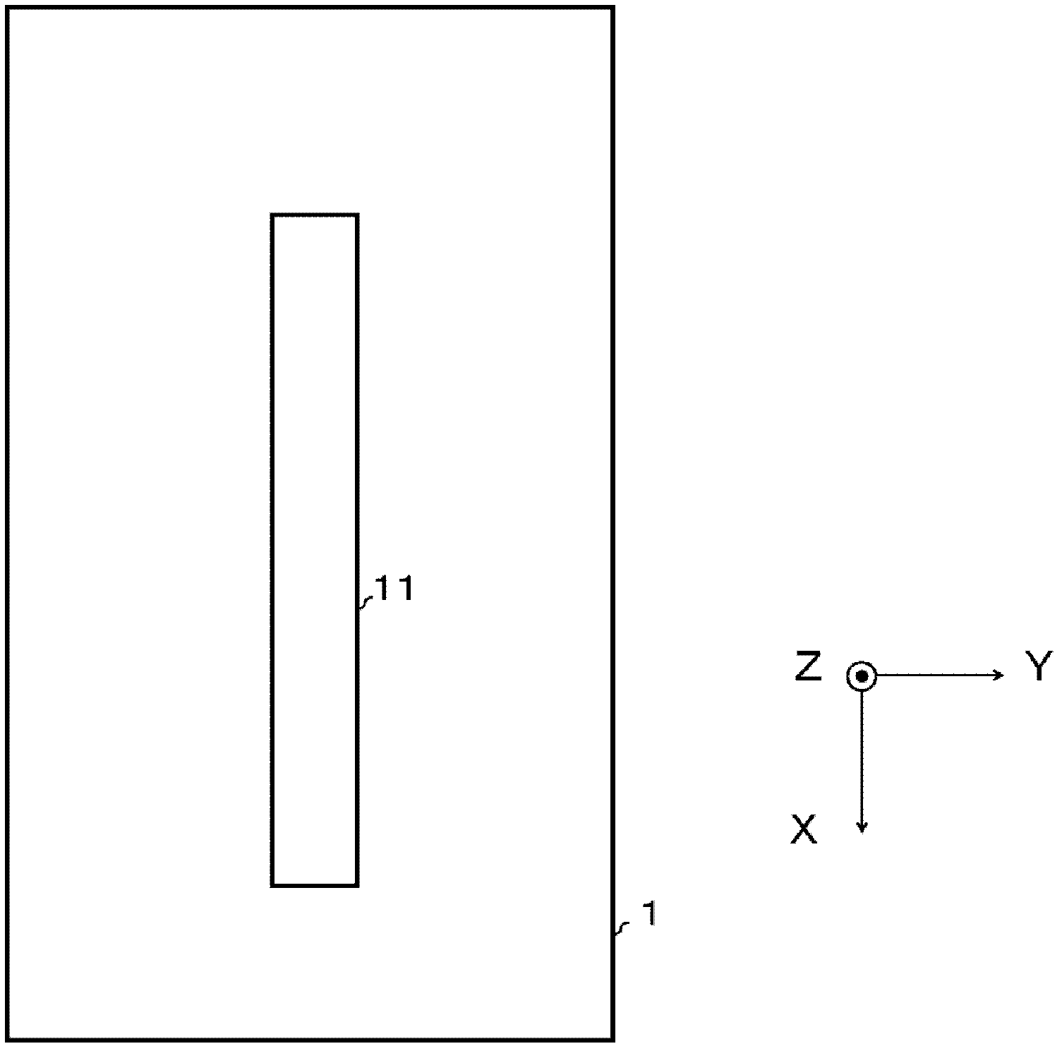
[0060] figure 1 A cross-sectional view of the plasma generating vessel 1 constituting one ion source of the present invention is depicted in . The X direction, the Y direction, and the Z direction intersect each other perpendicularly at one point, and the Z direction is a direction in which an ion beam 19 described later is extracted from the plasma generation container 1 .

[0061] A gas supply path 5 is connected to the wall surface of the plasma generation container 1 . A gas source 6 is attached to the gas supply path 5 via a valve 9 , and an ionizable gas serving as a raw material of an ion beam 19 is supplied from the gas source 6 . In addition, a gas flow regulator 7 (mass flow controller) is provided on the gas supply path 5 to adjust the supply amount of the ionizable gas supplied from the gas source 6 to the plasma generation container 1 .

[0062] On one side of the plasma generation vessel 1 , a U-shaped filament 2 is mounted via an insulating element 10 . Betwe...


PUM


Abstract

The invention provides an ion source and an ion implantation apparatus. Compared with conventional ion sources, the ion source provided by the invention has relatively few disconnected filaments (cathode) and can stably generate large-scale and high-current ion beams. The ion source (8) comprises a plurality of plasma generating containers (U11 to U42) each containing a slit-shaped opening part (11) and at least one cathode which is arranged at the front end part projecting to the inside and does not contact with plasma (3); a magnetic field generating mechanism (12) for generating the magnetic fields in the plasma generating containers (U11 to U42) along a longitudinal direction of the slit-shaped opening part (11); and a leading-out electrode (6) for leading out banding-shaped ion beams (19) with substantially-rectangular cross-section shape from the slit-shaped opening part (11). Viewed from a short-side direction of the substantially-rectangular cross-section, the banding-shaped ion beams (19) led-out from the plasma generating containers (U11 to U42) overlap with each other at one end thereof in the longitudinal direction of the substantially-rectangular cross-section.

Description

technical field [0001] The present invention relates to an ion source for generating ribbon-shaped (strip-shaped) ion beams and an ion implanter having the ion source. Background technique [0002] In recent years, the size of substrates (silicon wafers, glass substrates, etc.) on which ion implantation is performed has been increasing in size. In order to cope with such an increase in the size of the substrate, a technique for increasing the size of an ion beam irradiated on the substrate is being studied. [0003] As one of the methods for increasing the size of the ion beam irradiated on the substrate, it is conceivable to increase the size of the ion source that generates the ion beam. As such an ion source, a so-called barrel ion source described in Patent Document 1 having a plurality of permanent magnets and a plurality of filaments for generating a cusp magnetic field is used. [0004] Patent Document 1: Japanese Patent Laid-Open Publication No. 2000-315473 ( figu...

Claims


Application Information

Patent Timeline
IPC IPC(8): H01J37/317H01J37/08
CPCH01J27/04H01J27/14H01J37/08H01J37/3171H01J37/32009H01J37/32412H01J37/32422
Inventor 山下贵敏
Owner NISSIN ION EQUIP CO LTD
Why Eureka
Try Eureka