Eureka AIR delivers breakthrough ideas for toughest innovation challenges, trusted by R&D personnel around the world.

Object recognition method and recognition apparatus

An object recognition, object technology, applied in character and pattern recognition, image data processing, television and other directions, can solve the problem of large labor and achieve the effect of high-precision object recognition

Inactive Publication Date: 2012-12-19
HITACHI INFORMATION & TELECOMM ENG LTD
View PDF6 Cites 12 Cited by
  • Summary
  • Abstract
  • Description
  • Claims
  • Application Information

AI Technical Summary

Problems solved by technology

However, in this case, it is necessary to generate a database covering all patterns of distortion appearing on the fisheye image, and the generation of the database requires more labor than the generation of the database using a flat image.
[0012] Also, in the case described above, the hardware resources required for the database storing data with various patterns of distortion are also larger than when the distortion is not considered
[0013] Furthermore, in the above case, if the image of the object in any certain area on the fisheye image is detected, the database that stores the image data with all modes of distortion is directly used, since the above-mentioned database also includes objects with The distortion of the area is not similar to the database of the distorted object data, so it is still not possible to detect the object with sufficient detection accuracy

Method used


Image

  • Object recognition method and recognition apparatus
  • Object recognition method and recognition apparatus
  • Object recognition method and recognition apparatus

Examples


Embodiment Construction

[0035] Hereinafter, embodiments of the object recognition method and recognition device of the present invention will be described in detail with reference to the drawings. The present invention enables recognition of objects including persons using the entire fisheye image having a wide viewing angle without converting the fisheye image into a planar image.

[0036] Here, before describing specific embodiments of the present invention, an object recognition method based on the basic concept of the present invention will be described with reference to the drawings.

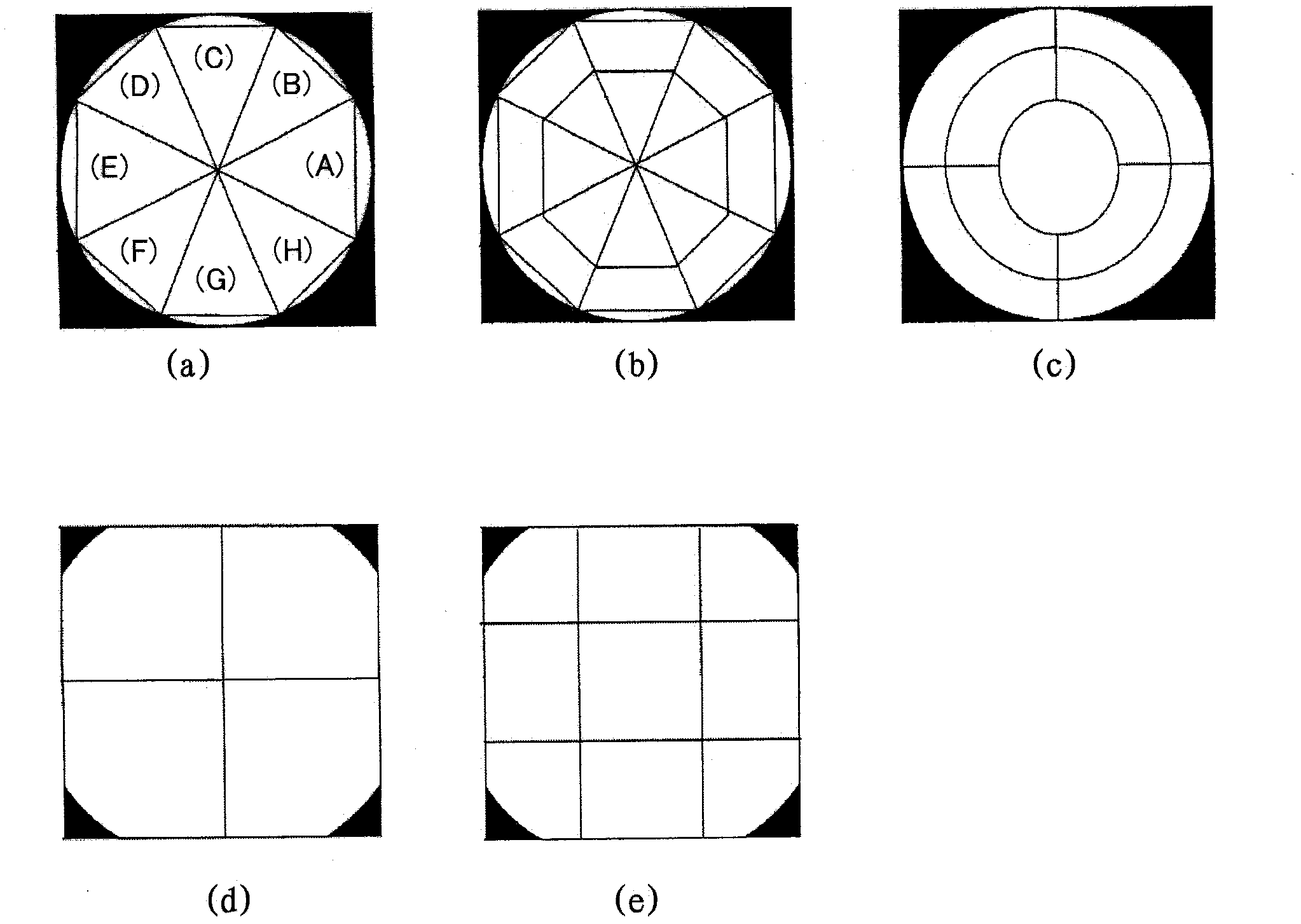
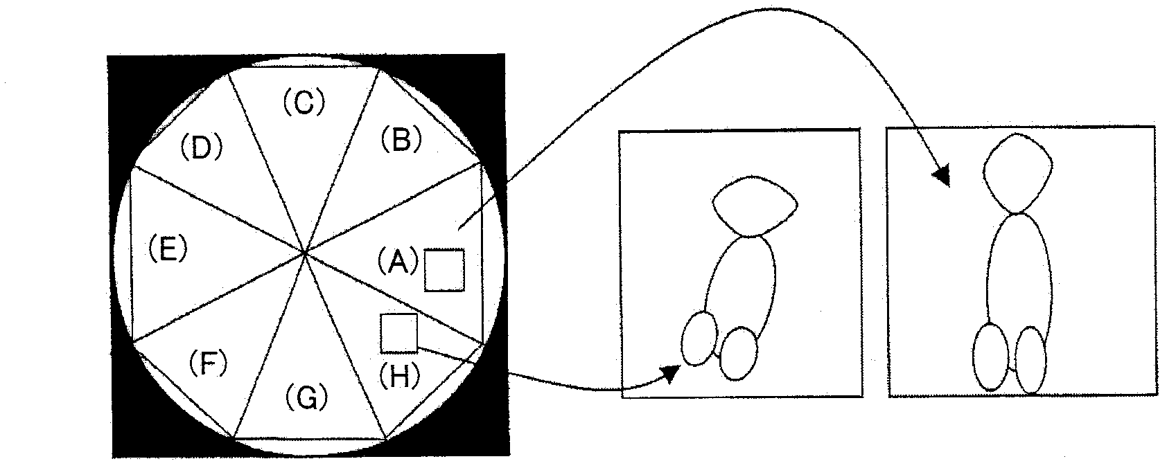
[0037] In the method of the first basic idea of ​​the present invention, in order to cope with the distortion of the fisheye image, the fisheye image is divided into a plurality of regions consistent with the direction of the distortion of the fisheye image, and each of the divided fisheye images is prepared. The databases corresponding to the regions are used to detect objects.

[0038] figure 1 It is a figure ...


PUM


Abstract

The invention provides an object recognition method and a recognition apparatus which can recognize objects by directly use a distorted fish-eye image for object recognition without projective conversion or image conversion based on corrective operation to the fish-eye image. A target fish-eye image (100) for object recognition is split (120) into regions in accordance with the direction of distortion of the target fish-eye image (100). An object recognition portion (130) performs object recognition by using databases (140) prepared in accordance with the regions respectively. The same process is applied to a plurality of target fish-eye images (110) created by rotation of the target fish-eye image (100). A detected coordinate transformation portion (150) restores the obtained position of an object into the original position by inverse rotation, and outputs a thus obtained result as a detection result. Accordingly, detection accuracy in object recognition can be improved, and the quality of data in databases can be reduced. Rotated object images required for database creation are used for creation of databases for object recognition for the fish-eye image.

Description

technical field [0001] The invention relates to an object recognition method and a recognition device, in particular to an object recognition method and a recognition device for recognizing a photographed object including a person in an image captured by a fisheye lens. Background technique [0002] The fisheye lens has the advantage of a wide field of view, but also has the disadvantage of including large distortion as the captured image moves from the center to the outside. Therefore, as a method for recognizing a captured object within an image captured by a fisheye lens, the prior art object recognition method used for a planar image with no or little distortion cannot be directly used. [0003] In order to be able to recognize a captured object in an image captured by a fisheye lens using the prior art object recognition method used for a planar image, it is generally known to convert a distorted image obtained by using a fisheye lens into a The technique of distorting...

Claims


Application Information

Patent Timeline
Patent Type & Authority Applications(China)
IPC IPC(8): G06K9/00G06K9/64G06V20/00G06V10/147
CPCG06K2209/29G06K9/209G06K9/00624G06K9/6201G06K9/6203G06V20/00G06V10/147G06V10/754G06V2201/11G06T3/00G06T7/00G06V10/40H04N23/00
Inventor 北口贵浩铃木邦彦上岛利明
Owner HITACHI INFORMATION & TELECOMM ENG LTD
Why Eureka
Eureka Blog
Learn More