Injection molding mold of container plastic part and injection molding method thereof

A technology for injection molds and plastic parts, which can be applied to household appliances, other household appliances, hollow objects, etc. It can solve the problems of difficult demoulding timing, low injection molding production efficiency, and easy deformation, so as to shorten the time required for demoulding, The effect of improving injection molding production efficiency and improving injection molding release performance

Active Publication Date: 2012-12-19
珠海市富林科技有限公司
View PDF8 Cites 5 Cited by
  • Summary
  • Abstract
  • Description
  • Claims
  • Application Information

AI Technical Summary

Problems solved by technology

Although currently compared with oil or natural gas plastics, plant plastics have disadvantages such as high manufacturing cost and easy deformation above 60°C, and have not been widely used; but it is certain that with the rapid development of science and technology, plant plastics will eventually become Will fully replace petrochemical plastics
As an ideal degradable and renewable novel material, polylactic acid plastic has developed rapidly in recent years, but its injection molding technology also has many problems to be solved; polylactic acid plastic, especially heat-resistant grade It takes a long time to crystallize, and the demoulding property is poor during injection molding. It is difficult to grasp the timing of demoulding. If it is too early, the workpiece will be deformed, and if it is too late, it will be stuck in the mold; The cycle time is about 3 minutes. Compared with the injection molding cycle of general petrochemical plastics, which is about 1 minute per mold, the injection molding production efficiency is very low.

Method used


Image

  • Injection molding mold of container plastic part and injection molding method thereof
  • Injection molding mold of container plastic part and injection molding method thereof
  • Injection molding mold of container plastic part and injection molding method thereof

Examples


Embodiment Construction

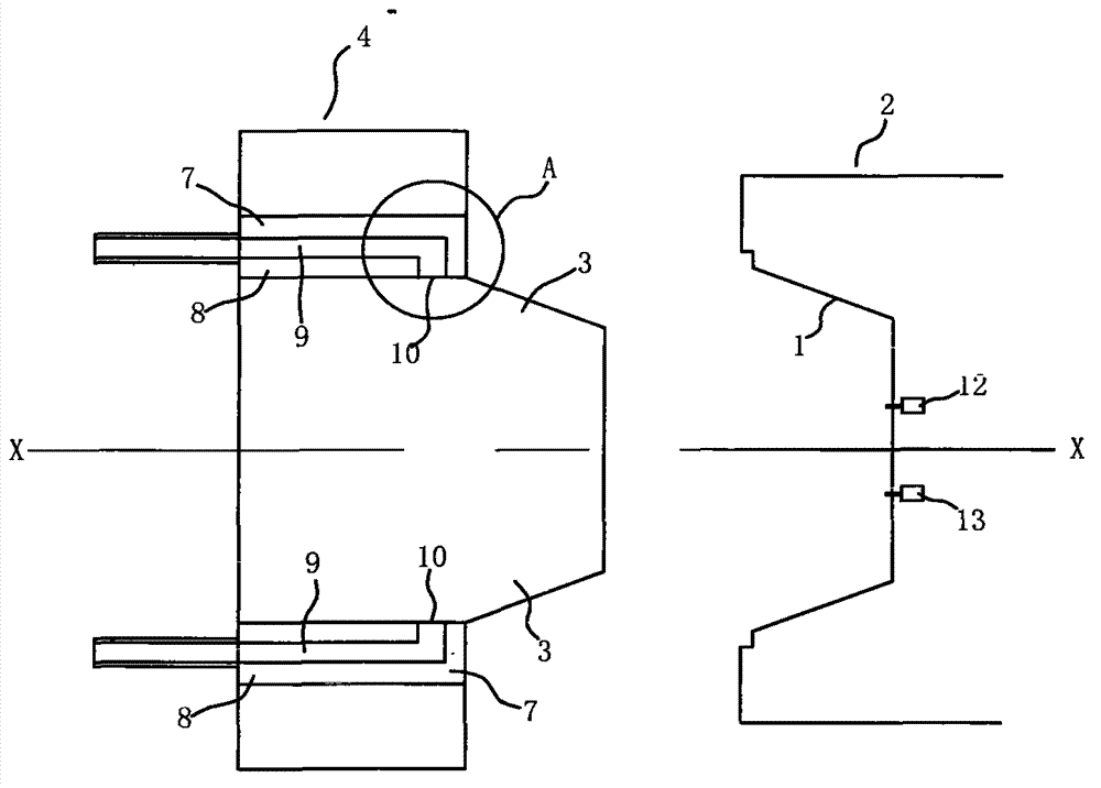
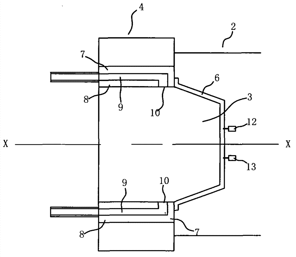
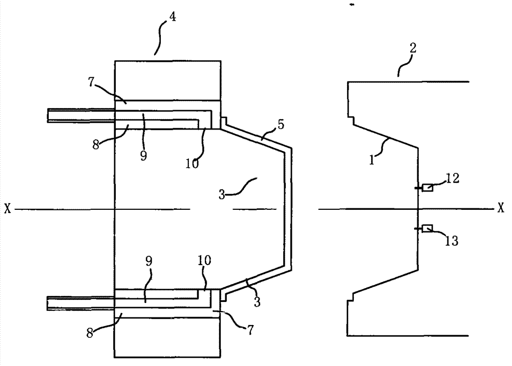
[0029] An injection mold for container plastic parts, such as Figure 1 to Figure 8 As shown, it includes a fixed mold 2 containing a cavity 1 and a movable mold 4 containing a core 3. The core 3 is in a convex shape corresponding to the inner surface of the container plastic part 5 to be injected, and the cavity is in the shape of the mold to be injected. The corresponding recessed shape of the outer surface of the container plastic parts. After the cavity 1 and the core 2 meet, their respective axes X overlap and form the molding space 6 of the plastic part 5. The movable mold 4 is along the circumference of the outer diameter of the core 3 At least two push rods are set to the position. The push rod 7 can move along the push rod slide hole 8 provided in the movable mold 4. The push rod 7 is provided with a flow channel hole 9 for compressed air introduction. The terminal turns in the direction of its axis X and forms an outlet 10 at the corresponding side wall of the push rod...


PUM


Abstract

The invention provides an injection molding mold of a container plastic part. A moving mold is provided with at least two pushing rods at the peripheral position along the outer diameter of a mold core of the moving mold; the pushing rods can move along pushing-rod sliding way holes of the moving mold and are internally provided with flow channel holes for leading in compressed air; the flowing channel holes bend from the final ends to the direction of the axis, and outlets are formed at the corresponding side walls of the pushing rods; when the pushing rods move to the set distance along the pushing-rod sliding way holes, and the outlets of the flow channel holes are communicated with a demolding space formed between the mold core and the container plastic part by movement of the pushing rods. An injection method comprises the following steps: the pushing rods move to the direction of a fixed mold along the pushing-rod sliding way holes, and simultaneously the compressed air is led into the flow channel holes; along with the movement of the pushing rods to the direction of the fixed mold, the plastic part separates from the mold core of the moving mold, simultaneously the compressed air enters the demolding space, and the compressed air in the demolding space further pushes the plastic part to separate from the mold core of the moving mold, so that the demolding action is quickly and fully finished.

Description

Technical field [0001] The invention relates to an injection mold for container plastic parts and an injection method thereof; in particular, a demolding mechanism and a demolding method thereof. Background technique [0002] Container plastic parts are generally manufactured by injection molds and injection molding processes. Because container plastic parts have a certain depth, there are often difficulties in demolding or demoulding takes a long time, which affects injection molding production efficiency. The prior art also uses compressed air for demolding, but most of them let the compressed air directly impact a certain part of the plastic product that has just been ejected. For example, Chinese patent document CN1473696A discloses a compressed air demolding method for injection molds. Its mold structure scheme is to open a valve cavity in the middle of the core. After the injection is completed and the movable mold and the fixed mold are separated, compressed air is injecte...

Claims


Application Information

Patent Timeline
Patent Type & Authority Applications(China)
IPC IPC(8): B29C45/43B29C45/76B29L22/00
Inventor 陈其明
Owner 珠海市富林科技有限公司
Why Eureka
Try Eureka