Motor seat mould of electric tool

A technology for electric tools and motor bases, applied in the field of electric tool motor base molds, can solve problems such as shaking, loosening, and inability to ensure concentricity, and achieve the effect of ensuring accuracy

Inactive Publication Date: 2012-12-19
KUSN TUOAN PLASTIC PRODS
View PDF4 Cites 4 Cited by
  • Summary
  • Abstract
  • Description
  • Claims
  • Application Information

AI Technical Summary

Problems solved by technology

The demoulding angle is more than 5 degrees, which will cause the lower part to be tight and the upp...

Method used


Image

  • Motor seat mould of electric tool

Examples


Embodiment 1

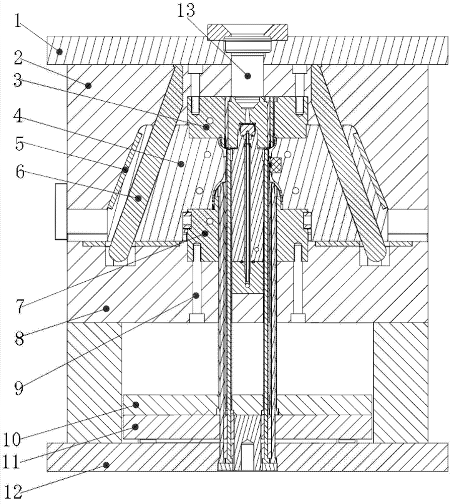
[0013] Such as figure 1 As shown, an electric tool motor seat mold includes an upper fixing plate 1, a female mold 2, a female mold insert 3, a slider 4, a wear-resistant block 5, an inclined guide post 6, a male mold core 7, and a male mold 8 , screw 9, upper thimble plate 10, lower thimble plate 11, lower fixed plate 12, hot pump nozzle 13, the lower thimble plate 11 and upper thimble plate 10 are installed on the lower fixed plate 12 from bottom to top, and the upper thimble A male mold 8 is installed above the plate 10, a female mold 2 is installed on the male mold 8, an upper fixing plate 1 is installed on the female mold 2, and oblique guide columns 6 are installed symmetrically in the cavities of the female mold 2 and the male mold 8. A slide block 4 is installed on the column 6, a male mold core 7 is installed in the cavity formed by the slide block 4 and the male mold 8, and a female mold core 3 is installed in the cavity formed by the slider 4 and the female mold 2. ...


PUM


Abstract

The invention relates to a motor seat mould of an electric tool, comprising fixing plates, moulds, guide columns, thimble plates and a nozzle, wherein a lower thimble plate (11) and an upper thimble plate (10) are arranged above a lower fixing plate (12) from bottom to top; a male mould (8) is arranged above the upper thimble plate (10) and a female mould (2) is arranged on the male mould (8); an upper fixing plate (1) is arranged on the female mould (2); inclined guide columns (6) are arranged in cavities of the female mould (2) and the male mould (8) in a bilateral symmetry manner; slide blocks (4) are mounted on the inclined guide columns (6) and a male mould core (7) is mounted in a cavity formed below the slide blocks (4) by the male mould (8); a female mould core embedding piece (3) is mounted in a cavity formed above the slide blocks (4) by the female mould (2); and the central position of the upper end of the female mould core embedding piece (3) is communicated with a hot nozzle (13) on the upper fixing plate (1). According to the motor seat mould of the electric tool, the accuracy of the size, and the concentricity and the roundness of a stator can be guaranteed.

Description

technical field [0001] The invention belongs to the technical field of electric motors, in particular to an electric tool motor seat mold. Background technique [0002] With the rapid development of modern industry, more and more electric products are used in the power devices of household and garden tools all over the world. In order to ensure that electric tools have low noise, good power, good performance and long life during use, this The use quality and service life of electric products put forward higher requirements. For example, the stator chamber of the motor seat and the motor stator must have precise concentricity and perfect roundness. In the traditional design of the stator chamber of the motor seat, the mold is considered. The demoulding slope is generally placed at a demoulding angle of more than 0.5 degrees, which will cause loosening or even shaking when the lower part is tight to the upper part when assembling with the stator, and the concentricity cannot b...

Claims


Application Information

Patent Timeline
IPC IPC(8): B29C45/26B29C45/40
Inventor 罗昌义罗昌国罗宣华
Owner KUSN TUOAN PLASTIC PRODS
Why Eureka
Try Eureka