Pathway structure of engine induction system

A technology of air intake system and engine, which is applied in the direction of engine components, machines/engines, mechanical equipment, etc., can solve problems such as rising costs, and achieve the effects of preventing combustion deterioration, reducing quantity, and reducing oil consumption

Inactive Publication Date: 2012-12-12
SUZUKI MOTOR CORP
View PDF9 Cites 0 Cited by
  • Summary
  • Abstract
  • Description
  • Claims
  • Application Information

AI Technical Summary

Problems solved by technology

The actual situation is that, therefore, taking measures to avoid interference with other parts by setting bending points at multiple locations of the air hose, the cost has to be increased as a result.

Method used


Image

  • Pathway structure of engine induction system
  • Pathway structure of engine induction system
  • Pathway structure of engine induction system

Examples


Embodiment Construction

[0022] Next, preferred embodiments of the passage structure of the intake system of the engine of the present invention will be described with reference to the accompanying drawings.

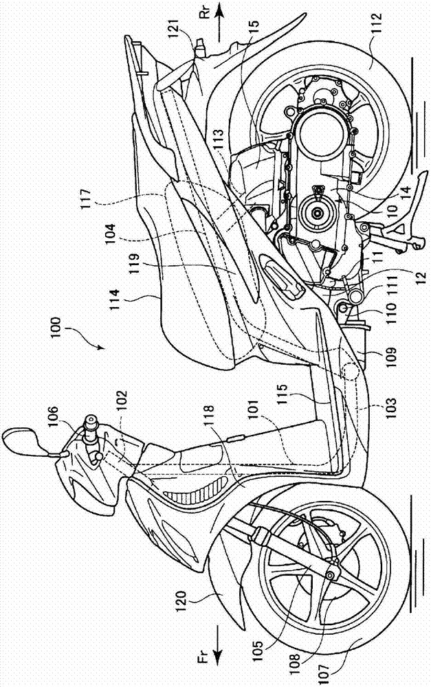
[0023] figure 1 It is a side view of the motorcycle of the present invention. First, use figure 1 To illustrate the overall structure of the motorcycle. Additionally, include figure 1 In addition, in the drawings used in the following description, the front of the vehicle is indicated by the arrow Fr, the rear of the vehicle is indicated by the arrow Rr, and the right side of the vehicle is indicated by the arrow R, and the left side of the vehicle is indicated by the arrow L, as necessary. .

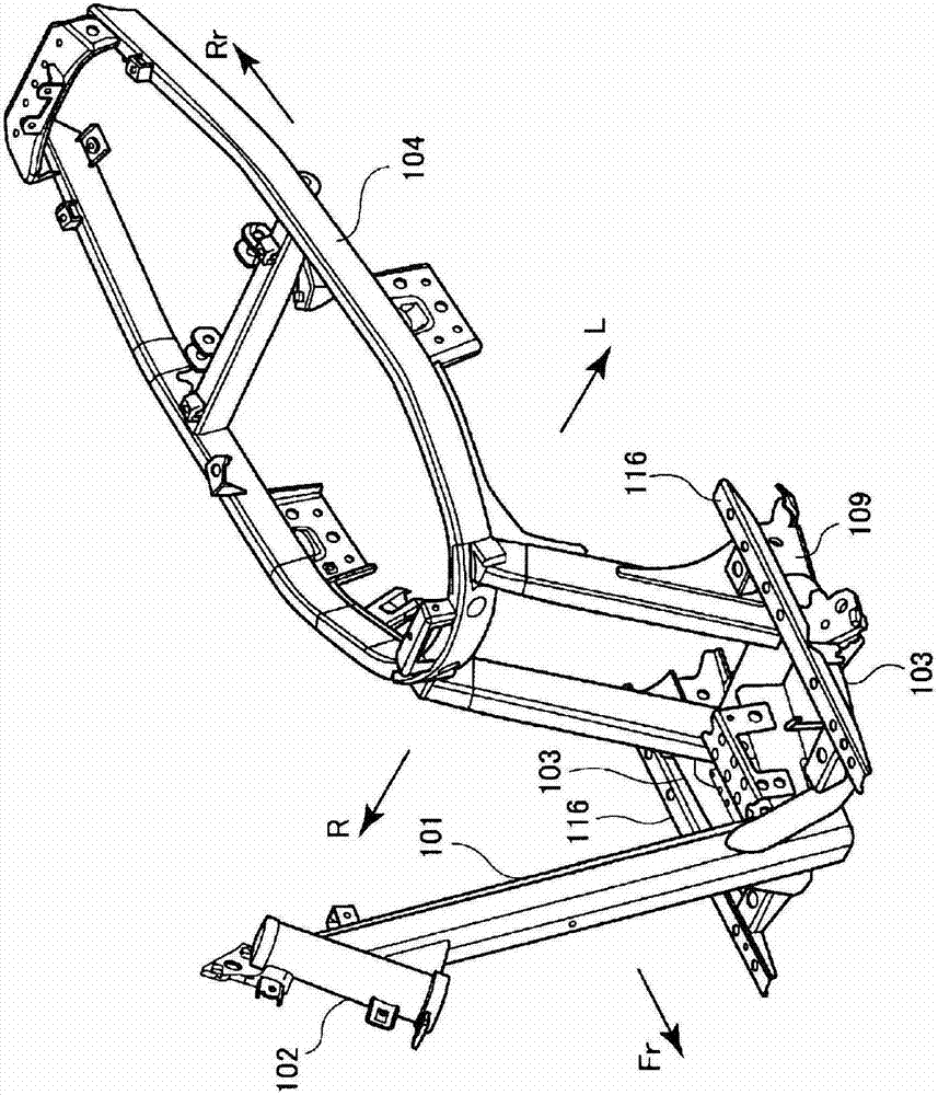
[0024] The vehicle 100 is constituted by forming a vehicle body frame with a plurality of vehicle body frames made of steel or aluminum alloy, and attaching various components to the vehicle body frames. In addition, as an example of the structure of the vehicle body frame, refer to figure 2 . The...


PUM


Abstract

The disclosed pathway structure of an engine induction system comprises: an air cleaner (15) disposed above a crank case (13); a carburetor (18) that is connected to an intake pathway that is lead to the front of the air cleaner (15); and an intake tube (19) that connects the carburetor (18) and the intake port of a cylinder head (13B); and has a breather hose (23) that is connected to a cylinder head cover (12A) and that is lead to the front of the air cleaner (15). The breather hose (23) passes above a throttle position sensor (22) in a lateral view, and is disposed in a manner so as to consistently descend towards the cylinder head. As a result, a pathway structure of an engine induction system is provided that achieves an appropriate tube disposition while being compact.

Description

technical field [0001] The invention relates to a structure of an air intake system passage of an engine in a motorcycle and other vehicles. Background technique [0002] In gasoline engines, etc., since the so-called blow-by gas becomes the cause of aging of engine oil, corrosion of metal, and even air pollution, it is returned to the intake side to mix with new air-fuel mixture for combustion, thereby avoiding this state. released into the atmosphere. [0003] For example, in the engine described in Patent Document 1, etc., a breather box is provided on the cylinder head cover, and blow-by gas is introduced from a breather inlet passing through the cylinder head cover through an oil separation chamber and a breather outlet in the breather box. The intake system of the engine. [0004] Also, in vehicles such as motorcycles, there is an engine in which an air cleaner is disposed above the crankcase, and an intake passage is linearly extended forward on the front surface of...

Claims


Application Information

Patent Timeline
Patent Type & Authority Applications(China)
IPC IPC(8): F01M13/00F02F7/00
CPCF01M13/025
Inventor 村松刚吉滨泽康平
Owner SUZUKI MOTOR CORP
Why Eureka
Try Eureka