
Device for recovering waste heat of waste water and bathing system using device

A waste heat recovery device, waste water technology, applied in applications, bathtubs, showers, etc., can solve problems such as energy waste, achieve the effects of reducing costs, saving energy, and preventing pipe clogging

Inactive Publication Date: 2012-12-12
成都恒新源暖通工程有限公司
View PDF7 Cites 4 Cited by
  • Summary
  • Abstract
  • Description
  • Claims
  • Application Information

AI Technical Summary

Problems solved by technology

[0003] At the same time, the temperature of the waste water after the guests wash their hair or take a bath generally can reach about 38 degrees Celsius, which is actually still very hot. A large amount of waste water is directly discharged into the sewer with a large amount of waste heat, causing energy consumption. Great waste

Method used


Image

  • Device for recovering waste heat of waste water and bathing system using device
  • Device for recovering waste heat of waste water and bathing system using device

Examples


specific Embodiment 1

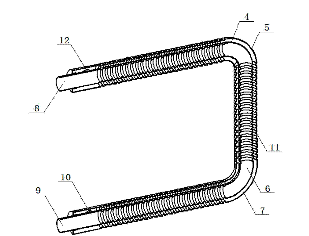
[0043] Such as figure 1 As shown, the wastewater waste heat recovery device includes a first sub-pipe 4 and a second sub-pipe 5, the second sub-pipe 5 is set outside the first sub-pipe 4; the inside of the first sub-pipe 4 is a first flow channel 6, the first The area between the pipe wall of the sub-pipe 4 and the pipe wall of the second sub-pipe 5 is the second flow channel 7; the two ends of the first sub-pipe 4 are respectively the waste water inlet end 8 and the waste water outflow end 9; the second sub-pipe One end of 5 is provided with water inlet 10, and the other end is provided with water outlet 12.

[0044] From the waste water inlet end 8 along the track of the first flow channel 6 to the waste water outflow end 9, the horizontal height of any intersection of the radial section and the axis near the waste water outflow end 9 in the first flow channel 6 is not higher than that in the first flow channel 6 Compared with it, it is the horizontal height of the intersec...

specific Embodiment 2

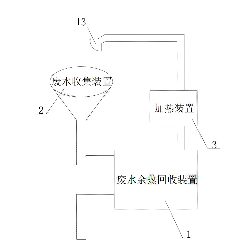
[0047] Such as figure 2 As shown, the bathing system includes a waste water waste heat recovery device 1; also includes a waste water collection device 2, a heating device 3 and a spray device 13, the waste water collection device 2 is connected to the waste water inlet 8; the water inlet pipe of the heating device 3 is connected to the water outlet 12 Connect, the outlet pipe of heating device 3 is connected with shower device 13.

[0048] The spraying device 13 is also provided with a communication port for connecting tap water and a regulating device for adjusting the ratio of tap water to the incoming water of the heating device.


PUM


Abstract

The invention relates to the field of energy recovery, and particularly relates to a device for recovering waste heat of waste water and a bathing system using the device. The device comprises a first sub pipe and a second sub pipe, wherein the second sub pipe is sleeved outsides the first sub pipe; a first runner is arranged inside the first sub pipe; a second runner is arranged between the first sub pipe and the second sub pipe; the both ends of the first sub pipe are respectively provided with a waste water inlet end and a waste water outlet end; a corrugated crease is arranged on the pipe wall of the first sub pipe; and a corrugated crease is further arranged on the pipe wall of the second sub pipe, which corresponds to the part provided with the corrugated crease on the first sub pipe. The bathing system comprises the device for recovering the waste heat of the waste water, a waste water collecting device, a heating device and a spraying device. When the device for recovering the waste heat of the waste water provided by the invention is in use, waste water flows through the first runner, and tap water flows through the second runner, so that the tap water absorbs the waste heat in the waste water; and an own original temperature is improved. The tap water enters the heating device for heating, so that energy can be saved.

Description

technical field [0001] The invention relates to the field of energy recovery, in particular to a waste heat recovery device for waste water and a bathing system using the device. Background technique [0002] Existing beauty salons, hotels, bathing and other industries generally use a lot of hot water. Generally, the water temperature during bathing is about 50 degrees Celsius, while the temperature of tap water is generally about 15 degrees Celsius. The tap water is heated from 15 degrees Celsius to 50 degrees Celsius. Need to consume a lot of energy, the cost is relatively large. [0003] At the same time, the temperature of the waste water after the guests wash their hair or take a bath generally can reach about 38 degrees Celsius, which is actually still very hot. A large amount of waste water is directly discharged into the sewer with a large amount of waste heat, causing energy consumption. Great waste. Contents of the invention [0004] The invention provides a wa...

Claims


Application Information

Patent Timeline
Patent Type & Authority Applications(China)
IPC IPC(8): F28D7/10F28F1/08A47K3/28
Inventor 周春潮
Owner 成都恒新源暖通工程有限公司
Learn More