Resin-made intake manifold, method for manufacturing resin-made intake manifold

An intake manifold and resin-made technology, which is applied in the manufacture of resin-made intake manifolds and the field of resin-made resin-made intake manifolds, can solve the problem of increasing the weight of resin-made intake manifolds and reducing the weight of intake manifolds. increase, cost increase, etc., to achieve the effect of increased durability, ensured strength, and suppressed deformation of the surrounding wall

Active Publication Date: 2012-12-12
AISAN IND CO LTD
View PDF9 Cites 8 Cited by
  • Summary
  • Abstract
  • Description
  • Claims
  • Application Information

AI Technical Summary

Problems solved by technology

Therefore, the cost increases due to the increase in welding man-hours
[0012] In addition, in order to ensure the strength of the welded part, it is generally considered to make the welded part thicker to prevent deformation corresponding to the applied load during vibration welding, but this requires an extra amount of resin, so the weight of the intake manifold made of resin increases.
In particular, in the resin intake manifold of Patent Document 3, a wall portion is formed below the weld line of the edge portion of the partition wall, and the weight of the resin intake manifold further increases.

Method used


Image

  • Resin-made intake manifold, method for manufacturing resin-made intake manifold
  • Resin-made intake manifold, method for manufacturing resin-made intake manifold
  • Resin-made intake manifold, method for manufacturing resin-made intake manifold

Examples


Embodiment Construction

[0052] Hereinafter, embodiments embodying the present invention will be described in detail with reference to the drawings.

[0053] Description of resin intake manifold

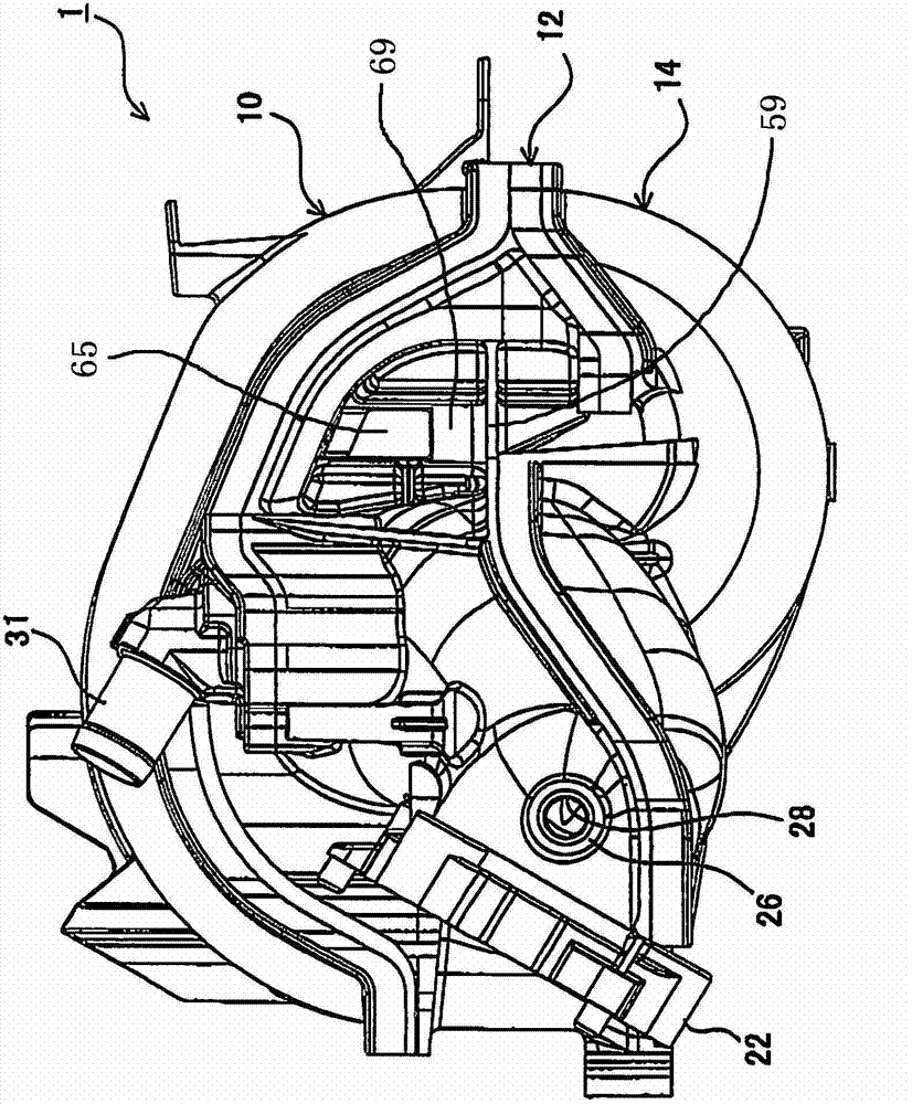
[0054] First, the overall outline of the resin-made intake manifold 1 will be described. here, figure 1 It is a front view of the intake manifold 1 made of resin. In addition, Figure 2(a) is viewed from the right side of the accompanying drawing figure 1 Figure 2(b) is a view of the resin intake manifold 1 shown from the left side of the drawing figure 1 The figure of the intake manifold 1 made of resin shown in Figure 2(c) is viewed from the upper side of the drawing figure 1 A diagram of the intake manifold 1 made of resin is shown. in addition, image 3 It is an exploded view of the resin intake manifold 1, Figure 4 yes figure 1 A-A sectional view of .

[0055] Such as Figure 1 ~ Figure 3 As shown, the intake manifold 1 made of resin is composed of an upper member 10 , a middle member 12 , a...


PUM


Abstract

The invention provides a resin-made intake manifold and a method for manufacturing resin-made intake manifold. The resin-made intake manifold can reduce manufacturing cost and reduce the volume of a surge tank. The invention provides a resin-made intake manifold (1) which has a central member (12) and a lower member (14), and the surge tank (18) is formed between the central member (12) and the lower member (14). The intake manifold (1) forms a branch passage (16) communicating with the surge tank (18), wherein the lower member (14) is an integrally molded product by the resin and comprises: a curve-shaped curved channel (20) which constitutes a part of the branch passage (16); and a wall portion (52), which is formed at the inner circumferential side of the curved shape of the curved conduit (20), from a passage port (34) of the curved channel (20) and the surge tank (18) to the central member (12) side, and forms the side wall of the surge tank (18).

Description

technical field [0001] The present invention relates to a resin-made intake manifold provided in an engine intake system, and specifically relates to a resin-molded resin-made intake manifold and a method for manufacturing the resin-made intake manifold. Background technique [0002] Patent Document 1 discloses a technology of a molding die having a rotatable sliding core as a molding die for a resin molded product having a curved pipe portion. In the technique of this patent document 1, after the molded product is formed, the clamping plate is lowered to separate the support member (main plate) from the slide core, a space is provided inside the molding die, and the slide mold is moved inside the space. The core rotates. And, after that, the molded product is ejected and taken out from the main plate. [0003] In addition, Patent Document 2 discloses a molding die capable of extracting a molded article having an arcuate cylindrical portion, and a technique of extracting a...

Claims


Application Information

Patent Timeline
IPC IPC(8): F02M35/104B29C45/03
CPCF02M35/104F02M35/10347F02M35/10321B29C45/4435F02M35/10354
Inventor 谷川裕纪松川将三大志万博章
Owner AISAN IND CO LTD
Why Eureka
Try Eureka