Eureka AIR delivers breakthrough ideas for toughest innovation challenges, trusted by R&D personnel around the world.

Boring head for boring non-circular holes

A technology for non-round holes and boring heads, which is applied in the direction of boring heads, boring/drilling, drilling/drilling equipment, etc.

Inactive Publication Date: 2012-12-12
周众
View PDF5 Cites 6 Cited by
  • Summary
  • Abstract
  • Description
  • Claims
  • Application Information

AI Technical Summary

Problems solved by technology

[0004] The invention particularly provides a boring head for boring non-circular pin holes. This mechanism is a new type of numerically controlled non-circular pin hole boring head based on magnetostrictive materials, which overcomes the defects of existing processing equipment and successfully solves the problem of The problem of precision and efficiency of pin hole machining

Method used


Image

  • Boring head for boring non-circular holes

Examples


Embodiment Construction

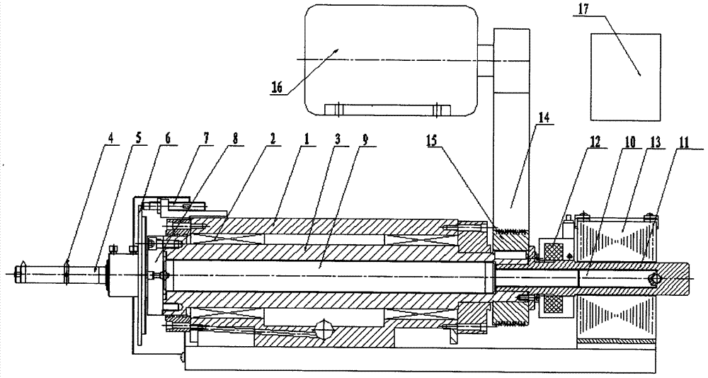
[0010] A boring head for boring non-circular holes described in this embodiment is characterized in that: the boring head is mainly composed of a housing (1), a boring head bearing (2), a hollow shaft (3), a boring tool ( 4), boring bar (5), displacement measuring disc (6), displacement sensor (7), spring plate (8), transition rod (9), magnetostrictive rod (10), non-magnetic material tube (11), A rotary encoder (12), a coil (13), a belt (14), a pulley (15), a spindle motor (16), a driver (17) and the like; wherein the transition rod (9) is inside the hollow shaft (3), The hollow shaft (3) is in the housing (1); the magnetostrictive rod (10) is in the non-magnetic material tube (11), and the non-magnetic material tube (11) passes through the inner ring of the coil (13) and the hollow shaft (3 ) is fixedly connected; one end of the transition rod (9) is connected with the magnetostrictive rod (10), and the other end is actively connected with the pit end of the spring plate (8);...


PUM


Abstract

A boring head for boring non-circular holes mainly comprises a casing (1), a boring head bearing (2), a hollow shaft (3), a boring tool (4), a boring bar (5), a displacement measuring panel (6), a displacement sensor (7), a spring plate (8), a transitional bar (9), a magnetostrictive rod (10), a non-magnetic material tube (11), a rotary encoder (12), a coil (13), a belt (14), a belt pulley (15), a spindle motor (16), a driver (17) and the like. The driver (17) controls magnitude of field current in the coil (13) to drive the magnetostrictive rod (10) to constrict, and elastic deformation of the spring (8) is changed by the aid of the transitional bar (9), so that the radial position of the boring tool (4) is changed, and the non-circular holes can be bored accurately according to feedbacks of the displacement sensor (7) and the rotary encoder (12).

Description

technical field [0001] The invention belongs to the technical field of numerical control machine tools, in particular to a boring head used for boring non-circular pin holes. technical background [0002] At present, in non-circular boring (such as the processing of non-circular pin holes in pistons), the boring tool is required to perform rapid and accurate micro-displacement movement in the radial direction. In use, a hydraulic mechanism is generally used to control the radial movement of the boring tool, such as Chinese patent CN2532929Y , CN1232732A, etc. The disadvantages of these structures are complex structures, poor precision and stability, and cannot be numerically controlled. [0003] The present invention utilizes the achievement of new materials to invent a mechanism to make the boring tool perform rapid, precise and digital micro-displacement movement along its radial direction, so as to process non-circular pin holes conveniently and practically. Contents o...

Claims


Application Information

Patent Timeline
IPC IPC(8): B23B29/034B23B41/04
Inventor 周众
Owner 周众
Why Eureka
Eureka Blog
Learn More