
Antenna arrangement for vehicles for transmitting and receiving

An antenna device and antenna technology, applied to antenna combinations with different interactions, suitable for antennas on movable objects, antennas and other directions, to achieve the effect of minimizing space requirements

Inactive Publication Date: 2012-12-05
ROBERT BOSCH GMBH
View PDF6 Cites 4 Cited by
  • Summary
  • Abstract
  • Description
  • Claims
  • Application Information

AI Technical Summary

Problems solved by technology

In the case of delay diversity, the same signal is transmitted simultaneously by at least two antennas on the transmit side, but each with a delay

Method used


Image

  • Antenna arrangement for vehicles for transmitting and receiving
  • Antenna arrangement for vehicles for transmitting and receiving
  • Antenna arrangement for vehicles for transmitting and receiving

Examples


Embodiment Construction

[0018] These embodiments describe antenna radiators that are suitable for one or more frequencies in the range of 0.5 GHz to 11 GHz.

[0019] Here, in one embodiment, the antenna radiator may be suitable for a frequency of 5.9 GHz, because the ETSI standard specifies communication between vehicles on this frequency. In another embodiment, other frequencies with correspondingly matched antennas can be used.

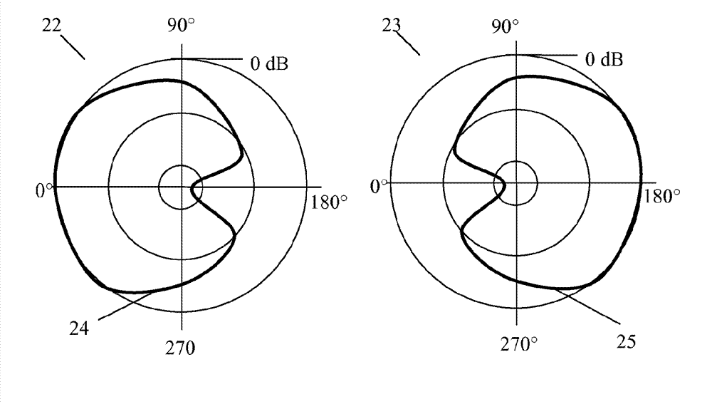
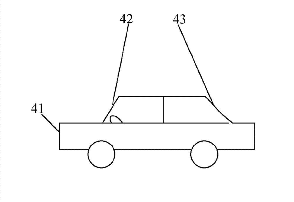
[0020] in figure 1 An antenna device 11 for an antenna housing of a vehicle is shown in FIG. The first antenna radiator 12 and the second antenna radiator 13 are positioned at both ends of the housing 17. Here, the first antenna radiator 12 is arranged at the front in the direction of the front of the vehicle in the housing 17 and the second antenna 13 is arranged at the rear in the direction of the rear of the vehicle in the housing 17. The first antenna radiator 12 has a preferred direction oriented forward. The second antenna radiator 13 has a preferred direction oriented...


PUM


Abstract

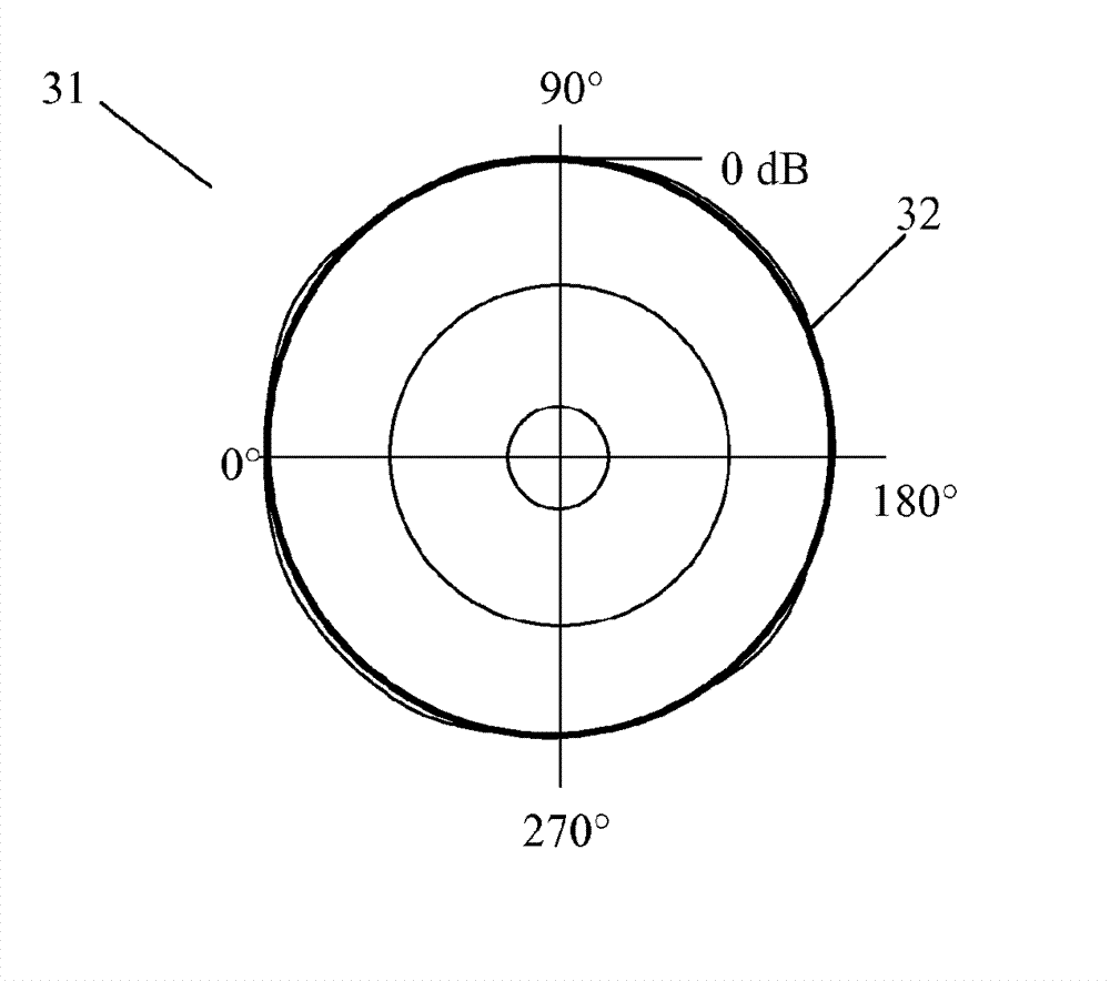
The invention relates to an antenna arrangement for vehicle-to-vehicle communication, wherein at least two antenna transmitters (12, 13), each having a unidirectional directional diagram, are positioned in such a manner that a combination of the unidirectional directional diagrams of the antenna transmitters generates a largely omnidirectional directional diagram by means of a method for transmitting and / or receiving.

Description

Technical field [0001] The invention is based on an antenna device for transmission and reception for a vehicle according to the preamble of the independent claim. Background technique [0002] From DE10209060A1, an antenna device for vehicles for reception in the GHz frequency range is known. The antenna device uses receive diversity in order to reduce the probability of interference. [0003] For example, from Future Transmitter / Receiver Diversity Schemes in Broadcast Wireless Networks, IEEE Communications Magazine 2008 by Zhang et al., diversity systems, multiple input multiple output systems, and orthogonal frequency division multiplexing are known. Diversity systems use two or more antennas in order to improve the quality and reliability of the radio connection. In the case of delay diversity, the same signal is simultaneously transmitted by at least two antennas on the transmitting side, but each has a delay. In the case of handover diversity, only one antenna is selected ...

Claims


Application Information

Patent Timeline
Patent Type & Authority Applications(China)
IPC IPC(8): H01Q1/32H01Q21/29
CPCH04B7/0404H01Q21/29H01Q1/325
Inventor T.汉森F.霍夫曼
Owner ROBERT BOSCH GMBH
Learn More