Window shade device

A blind, a pair of technology, used in door/window protection devices, shading screens, anti-glare equipment, etc., can solve the problem of overall window shading and other problems, and achieve the effect of stable pulling and storage.

Inactive Publication Date: 2012-12-05
ASHIMORI INDS
View PDF5 Cites 2 Cited by
  • Summary
  • Abstract
  • Description
  • Claims
  • Application Information

AI Technical Summary

Problems solved by technology

[0002] In the blind device, depending on the target window, there are restrictions on the arrangement of rails for guiding the blind due to spatial conditions, etc., and the entire window cannot be covered in the direction in which the blind is pulled out or stored. Happening

Method used


Image

  • Window shade device
  • Window shade device
  • Window shade device

Examples


Embodiment Construction

[0027] Hereinafter, a shade device according to an embodiment will be described.

[0028]

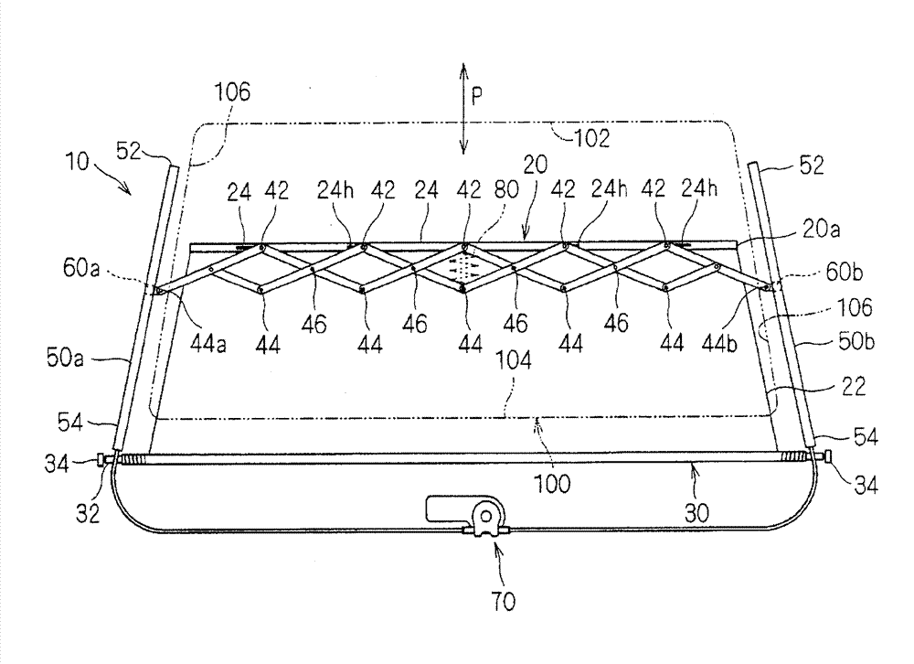
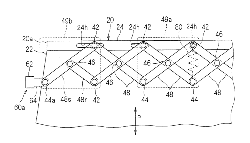
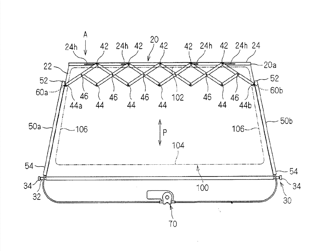
[0029] refer to Figure 1 ~ Figure 4 The configuration of the shade device 10 will be described. The blind device 10 is a device for covering a window 100 with a blind 20 .

[0030] The shade device 10 is a structure in which the shade 20 is moved by the pull-out member 40 , and the shade 20 is pulled out and stored relative to the storage device 30 , thereby covering the window 100 . A pair of runners (runners) 60a, 60b guided by a pair of rails 50a, 50b. In addition, the shade device 10 can draw the shade 20 over the pair of rotors 60a, 60b guided by the pair of rails 50a, 50b. This blind device 10 is more suitable for example, in the condition of space, the pair of rails 50a, 50b cannot be extended from one end to the other end of the window 100, or the pair of rotors 60a, 60b cannot be moved to the pair of rails 50a. , 50b of the front end portion 52 side of the constraints an...


PUM


Abstract

The disclosed window shade device is equipped with a window shade, a pair of rails that are provided such that the gap between said rails gradually becomes smaller from the base towards the tip, a storage device that is provided on the base side, a drawing member that supports the drawn end of the window shade, and a pair of runners that connect to each end of the drawing member and that can be moved along the respective rails. As the pair of runners moves, guided by the rails, the size of the drawing member is changed in the width direction of the window shade, the drawing end of the window shade is moved in the drawing / storage direction (P) and, when drawn, the drawn end is positioned on the drawing side by the pair of runners.

Description

technical field [0001] Patent Document 1 discloses a shade device for covering a gap through which light enters without being blocked in a drawn state of the shade. The window roller blind of Patent Document 1 includes a roller blind fixed at one end to a threaded take-up shaft, a tie rod assembly fixed to the other end of the roller blind, and a guide mechanism for guiding the tie rod assembly along a drawing path. The guide mechanism guides the tie rod assembly to a first rotational position at a rest position and to a second rotational position relative to the first rotational position at a functional position. In addition, the tie rod assembly part is provided with a formed plate having an end portion bent in a convex shape so that almost no gap remains at the functional position. Background technique [0002] In the blind device, depending on the target window, there are restrictions on the arrangement of rails for guiding the blind due to spatial conditions, etc., and...

Claims


Application Information

Patent Timeline
Patent Type & Authority Applications(China)
IPC IPC(8): E06B9/68B60J3/00
CPCB60J1/2027E06B9/66B60J1/2044E06B9/42E06B9/58B60J3/00E06B9/322
Inventor 畑浩一郎
Owner ASHIMORI INDS
Why Eureka
Try Eureka