
Sample feeding apparatus for ultra-high vacuum test

An ultra-high vacuum and sample delivery technology, which is applied in the preparation of test samples, analysis materials, instruments, etc., can solve the problems of difficult manufacturing, complex structure, low test efficiency, etc. simple effect

Inactive Publication Date: 2012-12-05
INST OF ELECTRONICS CHINESE ACAD OF SCI
View PDF5 Cites 9 Cited by
  • Summary
  • Abstract
  • Description
  • Claims
  • Application Information

AI Technical Summary

Problems solved by technology

The structure of the traditional ultra-high vacuum sample delivery device is complicated, and it is relatively difficult to manufacture. Moreover, since there is no observation hole on the sample holder and the observation port of the sample delivery rod plug, the process and status of the connection between the connecting rod of the sample joint and the sample holder cannot be observed in real time. The reliability is not easy to guarantee
[0003] In addition, the traditional ultra-high vacuum test sample feeding device needs to take the sample out of the vacuum chamber for measurement every time it is tested, which makes the sample need to be exposed to the atmosphere every time it is tested in a test cycle, which not only reduces the test efficiency , and the external environment will have an impact on the test results

Method used


Image

  • Sample feeding apparatus for ultra-high vacuum test
  • Sample feeding apparatus for ultra-high vacuum test
  • Sample feeding apparatus for ultra-high vacuum test

Examples


Embodiment Construction

[0043] A sample delivery device for ultra-high vacuum testing of the present invention will be further described in detail below in conjunction with the accompanying drawings.

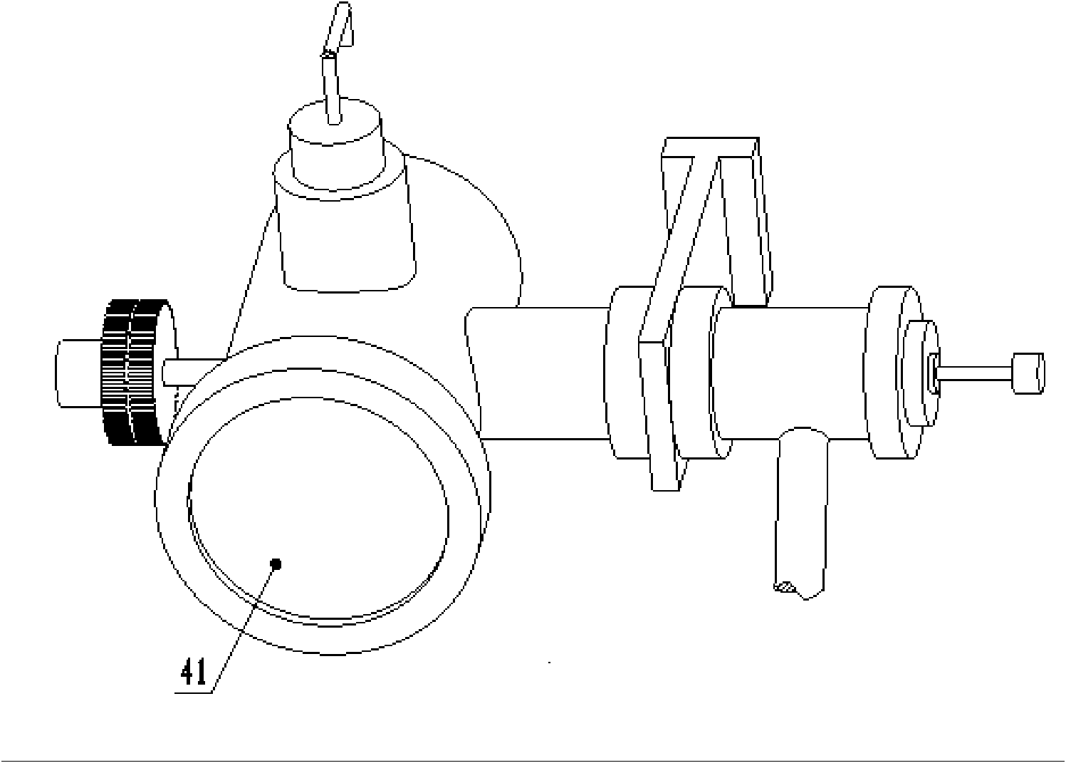
[0044] figure 1 Shown is a schematic view of the appearance of a sample delivery device for ultra-high vacuum testing.

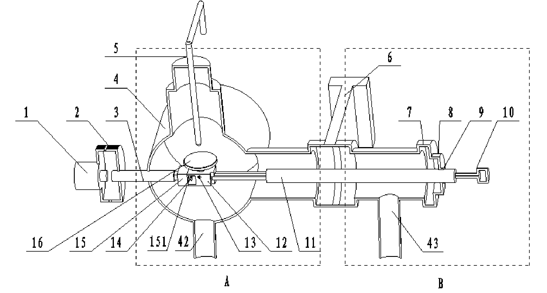
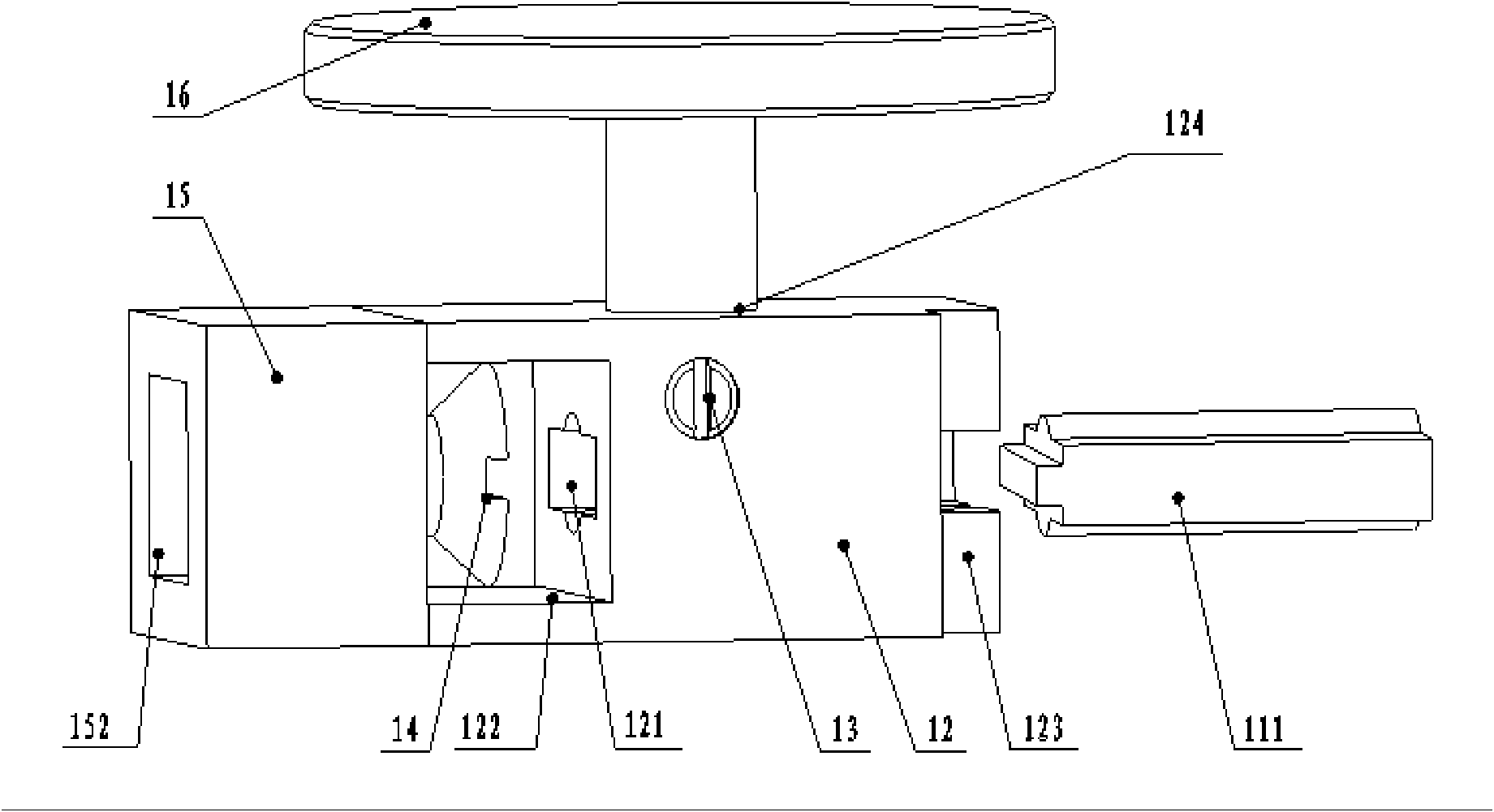
[0045]A sample delivery device for ultra-high vacuum testing, including a sample angle rotating wheel 1, a dial 2, a sample joint connecting rod 3, a vacuum tank 4, a test probe 5, a plug valve 6, and a low vacuum connecting flange 7 , sample feeding guide rod connection flange 8, sample feeding sealing cover 9, sample feeding adjustment handwheel 10, sample feeding rod 11, sample seat 12, sample fixing pin 13, sample connecting head connecting screw 14, sample connecting head 15, Sample 16. The sample 16 is placed in the sample placement hole 124 of the sample holder 12 , and the height adjustment of the sample 16 is realized through the asymmetrically arranged pins 13 on both sid...


PUM


Abstract

The invention discloses a sample feeding apparatus for an ultra-high vacuum test, and relates to a vacuum test technology. The apparatus comprises a vacuum tank, a sample seat, sample fixation pins, a sample feeding rod, a sample connection rod, connection screws, a sample connection head, and a gate valve. According to the apparatus, an axial end of the vacuum tank body is an observation window, a vertical cavity and a horizontal cavity are arranged in a radial direction, and the middle part of the horizontal cavity is provided with the gate valve. The left side of the gate valve is an ultra-high vacuum region, and the right side of the gate valve is a low vacuum region, wherein the two vacuum regions have air exhaust devices. A sample requiring detection is fixed on the upper surface of the sample seat through the fixation pin, the sample connection rod on the left side and the sample connection head form a separable fixation connection through the connection screw, and the sample seat and the sample connection head form a fixation connection so as to position inside a vacuum cavity. The sample connection rod, the sample connection head, the sample seat, and the sample feeding rod are horizontally and coaxially arranged in a line. The apparatus of the present invention has characteristics of simple structure, easy manufacturing and reliable sample feeding, and can be used for various vacuum tests and analysis equipment.

Description

technical field [0001] The invention relates to the technical field of vacuum testing, in particular to a sample delivery device for ultra-high vacuum testing. Background technique [0002] The sample delivery device is widely used in equipment such as vacuum testing and analysis. In order to obtain a practical and convenient sample delivery device for ultra-high vacuum, many scientific and technical personnel of research institutes have carried out relevant research. The structure of the traditional ultra-high vacuum sample delivery device is complicated, and it is relatively difficult to manufacture. Moreover, because there is no observation hole and the observation port of the sample delivery rod plug on the sample holder, the process and status of the connection between the connecting rod of the sample joint and the sample holder cannot be observed in real time. reliability is not easy to guarantee. [0003] In addition, the traditional ultra-high vacuum test sample de...

Claims


Application Information

Patent Timeline
IPC IPC(8): G01N35/10G01N1/28
Inventor 徐长有赵世柯邓峰
Owner INST OF ELECTRONICS CHINESE ACAD OF SCI
Learn More