
Charging heat-accumulating device of Stirling engine

A Stirling engine and heat storage device technology, which is applied to hot gas variable displacement engine devices, machines/engines, mechanical equipment, etc., can solve the problems of heating devices without heat, storage, and heat cannot be continuously supplied, so as to prevent The heat storage medium overflows and the effect of good heat dissipation effect

Inactive Publication Date: 2012-12-05
夏致俊
View PDF6 Cites 5 Cited by
  • Summary
  • Abstract
  • Description
  • Claims
  • Application Information

AI Technical Summary

Problems solved by technology

[0002] The Stirling engine is powered by a heating device and a cooling device arranged outside the Stirling engine. The heating device of the existing Stirling engine cannot store heat well because there is no special heat storage device. Especially when the Stirling engine is applied to mobile equipment (such as a vehicle driven by the Stirling engine), it often affects the normal use of the Stirling engine because the heat cannot be continuously supplied.

Method used


Image

  • Charging heat-accumulating device of Stirling engine
  • Charging heat-accumulating device of Stirling engine
  • Charging heat-accumulating device of Stirling engine

Examples


Embodiment 1

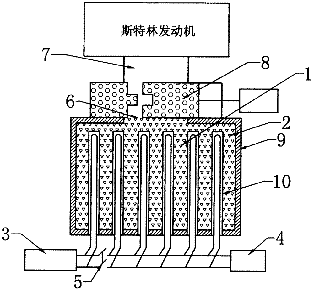
[0023] like figure 1 As shown, the charge heat storage device of the Stirling engine of the present invention includes a heat storage chamber 1, an insulation layer 9 is arranged outside the heat storage chamber, molten salt 2 is housed in the heat storage chamber, and a plurality of An electric heating device 10 composed of electric heating tubes; the electric heating device is arranged in two parts, one part is a low-power heating device with a small number of electric heating tubes, and the other part is a high-power heating device with a large number of electric heating tubes. It is connected with high-power power supply terminal 4, which can be used to connect to the power supply of a specially set high-power charging station for electric vehicles. The input end of the low-power electric heating device is connected to the low-power power supply terminal 3, which can be used to connect to ordinary civilian power supplies; the input end of the high-power heating device is c...

Embodiment 2

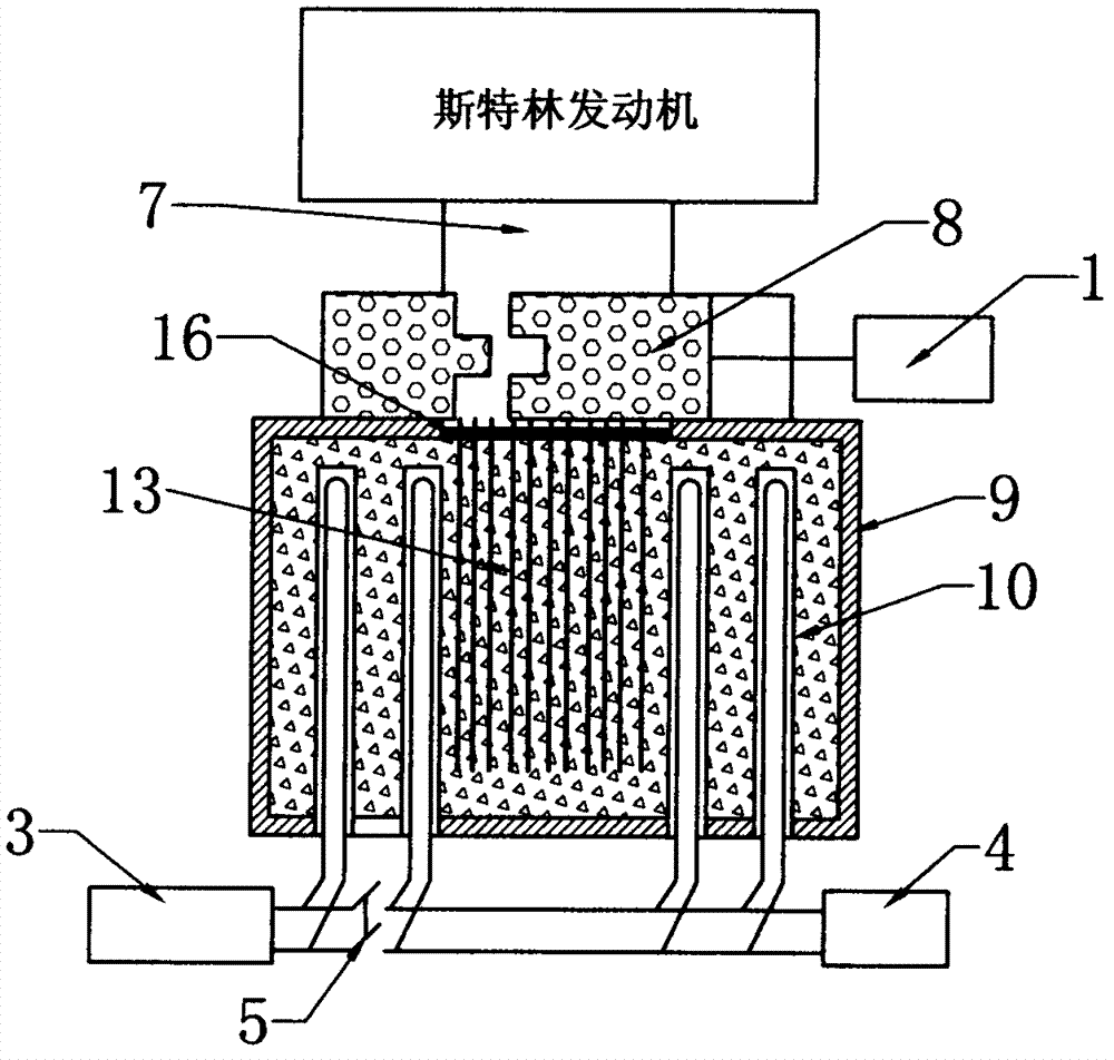
[0025] like figure 2 As shown, on the basis of the first embodiment, a partition 16 is further provided at the opening 6 of the heat storage cavity, and a heat sink 13 is provided on the partition.

Embodiment 3

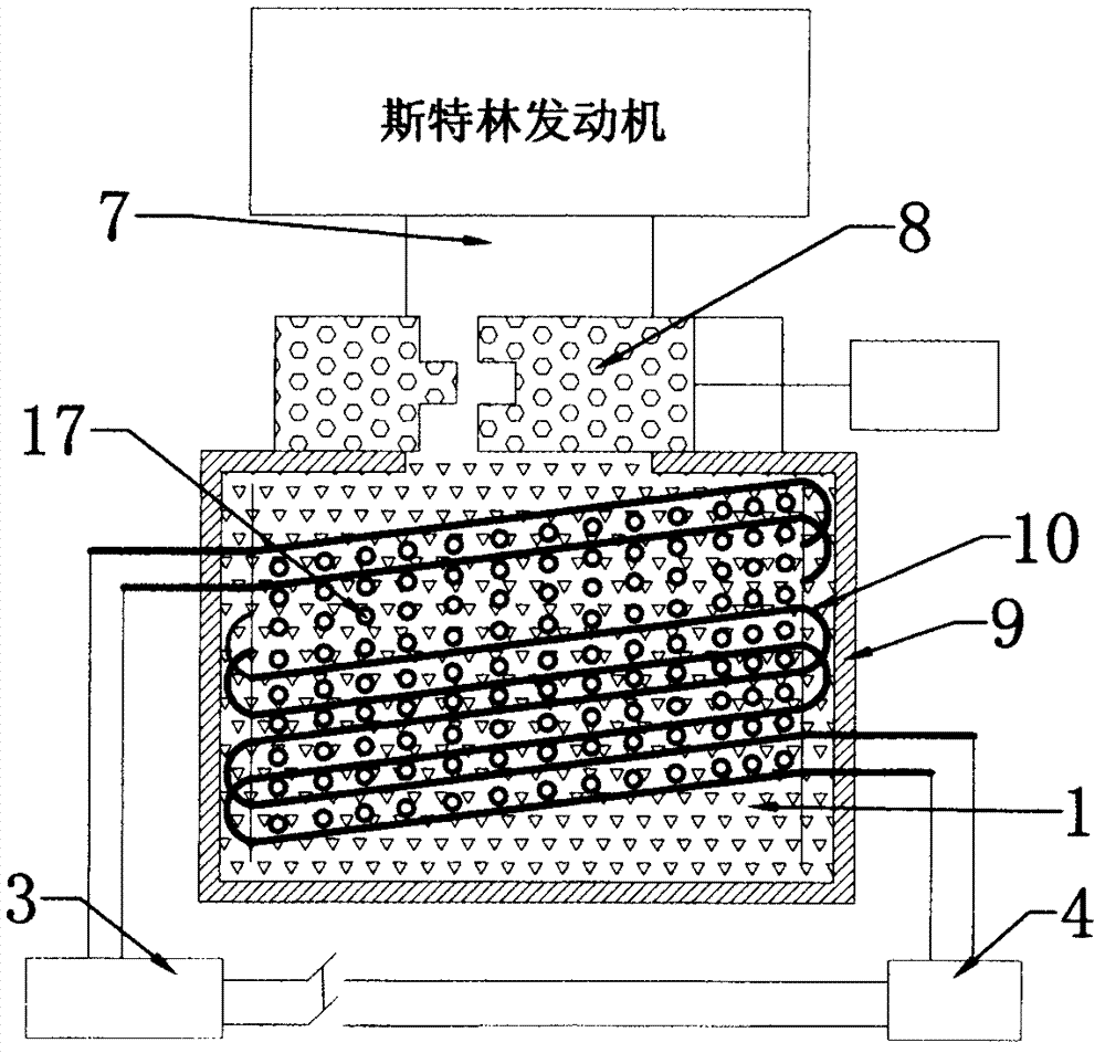
[0027] like image 3 As shown, the difference between it and Embodiment 1 is that the electric heating device 10 adopts intermediate frequency coils; the intermediate frequency coils are provided with two groups, one group is a low-power intermediate frequency coil, and the other group is a high-power intermediate frequency coil, respectively connected to the low-power power supply terminal and High-power power supply terminal; at the same time, a metal ball 17 is arranged in the intermediate frequency coil.


PUM


Abstract

The invention relates to a charging heat-accumulating device of a Stirling engine. The charging heat-accumulating device is used for supplying heat to the Stirling engine. The charging heat-accumulating device comprises a heat-accumulating cavity, wherein a heat-accumulating medium is arranged in the heat-accumulating cavity; an electric heating device is arranged in the heat-accumulating cavity; a heat-sink port which is communicated with a heat absorption end of the Stirling engine is formed on the heat-accumulating cavity; and a valve of which the aperture is adjustable is arranged at the heat-sink port. The charging heat-accumulating device of the Stirling engine has the advantages that the heat can be quickly re-supplied by the heat-accumulating medium and slowly released, and requirements on long-time stable operation of the Stirling engine under the condition that the heat is not re-supplied can be met, so the Stirling engine is applicable to various occasions, and particularly, the superiority of the device can be shown on mobile equipment.

Description

technical field [0001] The invention relates to a charge heat storage device of a Stirling engine used to provide heat source for Stirling engine. Background technique [0002] The Stirling engine is powered by a heating device and a cooling device arranged outside the Stirling engine. The heating device of the existing Stirling engine cannot store heat well because there is no special heat storage device. Especially when the Stirling engine is applied to mobile equipment (such as vehicles driven by the Stirling engine), the normal use of the Stirling engine will often be affected due to the inability to continuously supply heat. Contents of the invention [0003] The technical problem to be solved by the present invention is to provide a charge heat storage device for a Stirling engine that can store heat and provide a long-term continuous heat source for the Stirling engine. [0004] In order to solve the above-mentioned technical problems, the charging heat storage dev...

Claims


Application Information

Patent Timeline
IPC IPC(8): F02G1/053
Inventor 夏致俊
Owner 夏致俊
Learn More