
Optical film and manufacturing method thereof

A technology of optical diaphragm and manufacturing method, which is applied in the direction of optical elements, other household appliances, household appliances, etc., can solve the problems of high cost, inconvenient manufacture and installation of multiple diaphragms, etc., achieve good thermal expansion and contraction rate, and manufacture And the effect of easy installation and cost reduction

Inactive Publication Date: 2012-11-28
KONKA GROUP
View PDF6 Cites 11 Cited by
  • Summary
  • Abstract
  • Description
  • Claims
  • Application Information

AI Technical Summary

Problems solved by technology

However, it is very inconvenient to manufacture and install such a structure using multiple diaphragms, and the cost is relatively high

Method used


Image

  • Optical film and manufacturing method thereof
  • Optical film and manufacturing method thereof
  • Optical film and manufacturing method thereof

Examples


Embodiment Construction

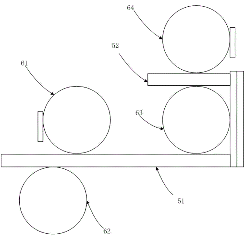
[0017] See figure 1 . The optical film of the present invention comprises an optical film substrate 1, a prism structure 2 and a microlens structure 3, and the prism structure and the microlens structure are respectively arranged on two opposite surfaces of the optical film substrate. In this specific embodiment, the prism structure 2 is disposed on the upper surface of the optical film substrate 1 , and the microlens structure 3 is disposed on the lower surface of the optical film substrate 1 . The optical film substrate is an optical grade film substrate such as PET or PC. Both the prism structure and the microlens structure are formed on the optical film substrate by rolling and curing UV glue through rollers.

[0018] When used in backlight modules, DBEF (Dual Brightness Enhancement Film, emissive polarizer) 4 can also be added to the optical film, such as figure 2 shown.

[0019] See image 3 , which shows a principle of manufacturing the above-mentioned optical fi...


PUM


Abstract

The invention discloses an optical film and aims to provide a composite film, which is applicable to a backlight module, replaces the conventional architecture consisting of a prism sheet and a diffusion sheet or a micro-lens sheet and cannot generate ripple after being heated. The optical film comprises an optical film base material, a prism structure and a micro-lens structure, wherein the prism structure and the micro-lens structure are respectively arranged on two opposite surfaces of the optical film base material. The invention also discloses a manufacturing method of the optical film. The invention can be applied to the backlight module and a liquid crystal display screen.

Description

technical field [0001] The invention relates to a backlight module, in particular to an optical film and a manufacturing method thereof. Background technique [0002] Nowadays, liquid crystal display technology is becoming more and more mature, and TVs have also changed from using traditional picture tubes to current LCD screens. Since the LCD display is a passive light-emitting display, and the LCD itself does not emit light, the LCD needs a backlight module to provide a light source. According to the type of light source, the backlight module can be divided into CCFL backlight module, LED backlight module and so on. Since the general light source is a point light source or a line light source, in common applications, it is necessary to use an optical film to achieve effects such as light enhancement and diffusion. A common backlight module will require other films such as a diffuser, a prism, or a microlens. The multi-diaphragm structure is a commonly used diaphragm col...

Claims


Application Information

Patent Timeline
IPC IPC(8): G02B5/04G02B5/02B29D11/00
Inventor 姜洪波
Owner KONKA GROUP
Learn More