Rotary dimming mechanism

A rotating and shading column technology, which is applied in the direction of light source fixing, lighting devices, lighting device components, etc., can solve the problems of unstable light shape, high noise of dimming action, etc., and achieve perfect dimming function and high reliability , The effect of stable dimming process

Active Publication Date: 2014-03-12
HASCO VISION TECHNOLOGY CO LTD
View PDF1 Cites 0 Cited by
  • Summary
  • Abstract
  • Description
  • Claims
  • Application Information

AI Technical Summary

Problems solved by technology

[0007] The purpose of the present invention is to provide a rotary dimming mechanism with a stable dimming process and no electromagnetic valve noise, and a rotary shading column driven by a stepping motor worm gear to realize the change of the cut-off line and solve the problem of switching between the far and near beams of the existing car lights The mechanism dimming process and light shape are unstable, and the technical problem of high noise in dimming action

Method used


Image

  • Rotary dimming mechanism
  • Rotary dimming mechanism
  • Rotary dimming mechanism

Examples


Embodiment Construction

[0027] In order to better understand the above technical solutions of the present invention, a further detailed description will be given below in conjunction with the drawings and embodiments.

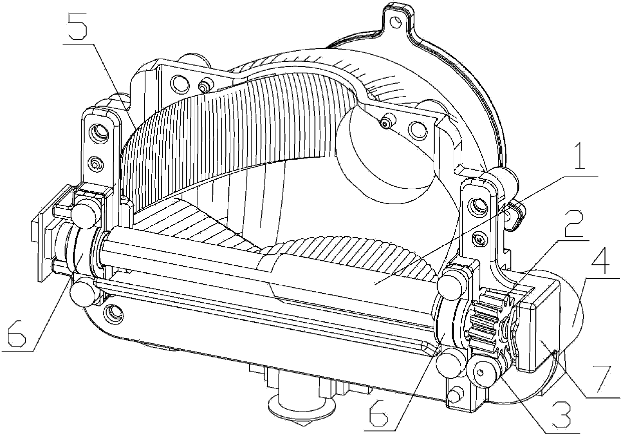
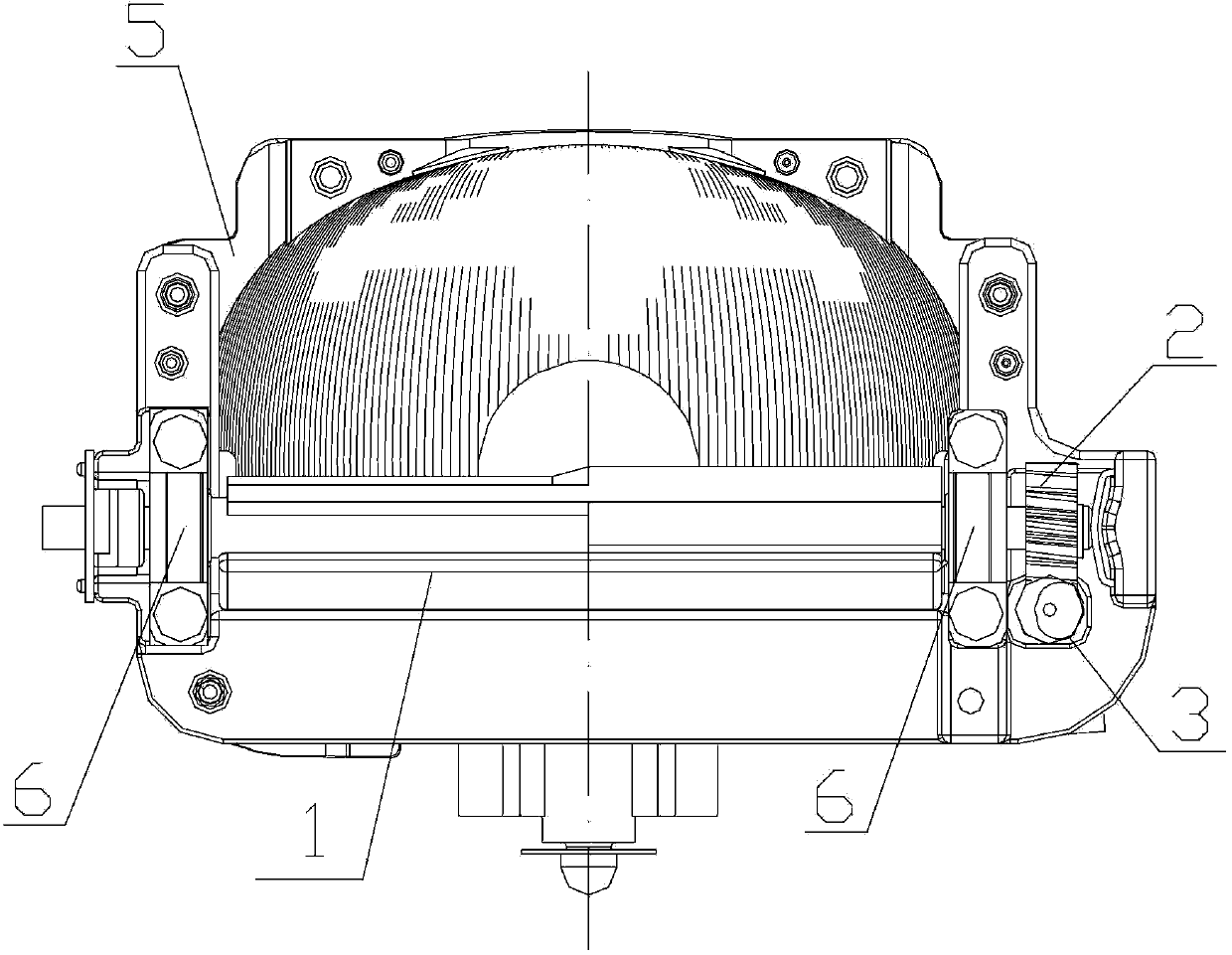
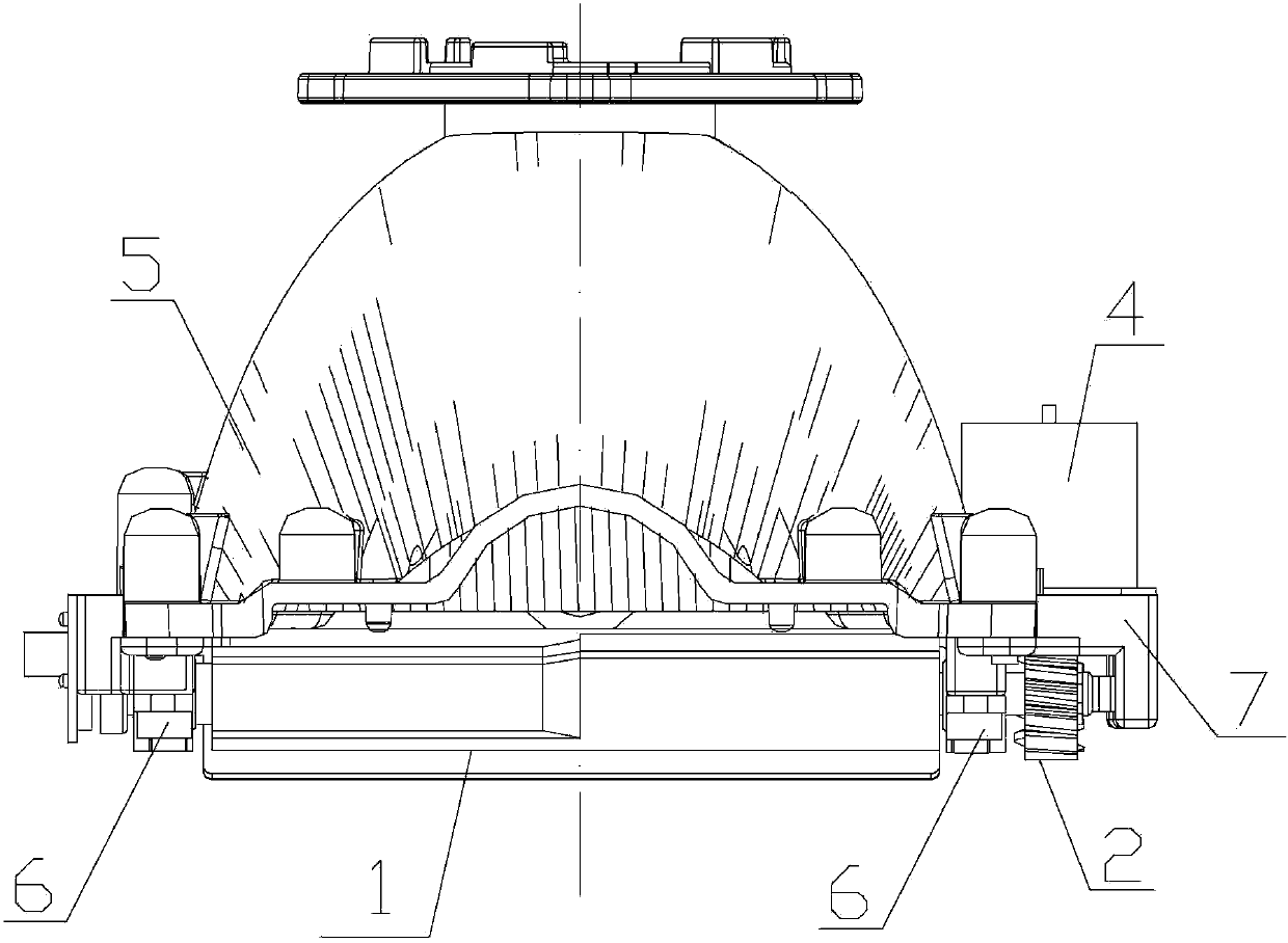
[0028] The rotary dimming mechanism of the present invention is connected to the car lamp housing 5 and is composed of a shading element, a transmission assembly and a drive motor. The shading element is placed on the light path of the car lamp, and its structure is as follows: Figure 1 to Figure 3 shown. In this embodiment, the shading element is a shading column 1, the transmission assembly is a worm-gear and worm transmission pair composed of worm gear 2 and worm 3, and the driving motor is a stepping motor 4; 3 is fixedly connected to the rotating shaft of the stepping motor 4, and the stepping motor 4 is fixedly connected to the lamp housing 5 through the fixing bracket 7.

[0029] according to Figure 1 to Figure 3 As shown in the embodiment of the rotary dimming mechanism of...


PUM


Abstract

The invention discloses a rotary dimming mechanism, which relates to the functional characteristic or a part an illuminating device or a system thereof, in particular to a rotary dimming mechanism for changing the characteristic and distribution of luminescence by adjusting a part. The rotary dimming mechanism comprises a light shielding column 1, a worm wheel 2, a worm 3 and a stepping motor 4, wherein the worm wheel 2 is fixedly connected to the shaft end of the light shielding column 1; the worm 3 is fixedly connected to a revolving shaft of the stepping motor 4; the stepping motor 4 is fixedly connected to a vehicle lamp shell 5 through a fixing bracket 7; the stepping motor 4 is in meshed transmission connection with the light shielding column 1 through the worm 3 and the worm wheel 2; the light shielding column 1 rotates around a rotating center thereof, and shows different section shapes on the light path of a vehicle lamp; and the light shielding column is designed with different specific section shapes at different rotating angles, so that a light shielding form which is consistent with far and near light requirements is formed. The rotary dimming mechanism disclosed by the invention has the advantages of stable dimming process, lose dimming action noise, self-locking function, higher reliability and capability of realizing dimming of multiple light forms.

Description

technical field [0001] The present invention relates to a functional feature or component of a lighting device or its system, in particular to a rotary dimming mechanism for changing the characteristics and distribution of luminous light by means of adjusting components. Background technique [0002] The existing far and low beam switching mechanism of the car lamp realizes dimming by controlling the position of the sun visor. Most dimming mechanisms use a solenoid valve as a control element, and the far and near light positions of the visor are switched through the expansion and contraction of the solenoid valve. [0003] Chinese utility model patent "automotive lamp with far and near beam switching mechanism" (utility model patent number: ZL200620070826.6 publication number: CN2890620) discloses an automotive lamp with a far and near beam switching mechanism, mainly including reflectors, light sources), accessories Optical lens, the reflector is equipped with a rear end b...

Claims


Application Information

Patent Timeline
Patent Type & Authority Patents(China)
IPC IPC(8): F21V14/00F21W101/10
Inventor 于世杰朱明华郭田忠
Owner HASCO VISION TECHNOLOGY CO LTD
Why Eureka
Try Eureka