
Lens calibration system and method thereof

A technology for calibrating systems and lenses, applied in installation, optics, focusing devices, etc., can solve the problems of long focusing time, high production costs, and high labor costs, and achieve the effect of reducing production costs

Inactive Publication Date: 2012-11-21
ALTEK CORP
View PDF4 Cites 29 Cited by
  • Summary
  • Abstract
  • Description
  • Claims
  • Application Information

AI Technical Summary

Problems solved by technology

[0010] The object of the present invention is to provide a lens calibration system and its method to solve the problems of long working hours, high manpower cost or high production cost of traditional lens focus machines

Method used


Image

  • Lens calibration system and method thereof
  • Lens calibration system and method thereof
  • Lens calibration system and method thereof

Examples


Embodiment Construction

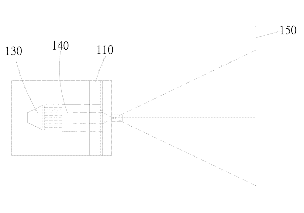
[0054] Please also refer to figure 2 and image 3 ,in figure 2 It is a block diagram of an embodiment of the lens calibration system of the present invention. image 3 It is a schematic diagram of an embodiment of the lens calibration system of the present invention. figure 2 Among them, the lens calibration system 200 includes a target pattern display 210 , a calibration platform 220 , an image test module 230 and a motor module 240 . The target pattern display 210 is used to display a target pattern 211 . The calibration platform 220 is used to place a lens 221 to be calibrated, wherein the calibration platform 220 further includes a calibration mechanism 222 . Wherein, the calibration mechanism 222 is shown as being mechanically connected with the lens 221 to be calibrated. The image testing module 230 includes an image capturing unit 231 and a computing module 232 . In consideration of optical factors, the calibration platform 220 is arranged parallel to the targe...


PUM


Abstract

The invention discloses a lens calibration system and a method thereof. The lens calibration system comprises a calibration platform which comprises a calibration mechanism, a lens to be calibrated is placed on the calibration platform, an image test module captures a target pattern on a target pattern display through the lens to be calibrated so as to obtain an imaging pattern, the image test module performs parameter calculation on the imaging pattern and sends an adjusting signal according to the calculation result, and a motor module receives the adjusting signal and drives the calibration mechanism to calibrate the lens to be calibrated according to the adjusting signal. The lens calibration system and the method thereof can solve the problems of long focusing working hour, high labor cost or production cost of the existing lens focusing machine.

Description

technical field [0001] The present invention relates to a lens calibration system and its method, in particular to a lens calibration system and its method for adjusting the focal length of the lens with an auto-focus system according to the capture result of the target pattern. Background technique [0002] An ideal photographic lens must have: a. Points must be imaged as points. b. The surface directly in front must be perpendicular to the optical axis to form a positive surface. c. The image formed by the subject and the lens must be similar. d. The color of the image must be presented realistically. In theory, as long as the area outside the optical axis on the imaging surface is ignored, standard imaging can be produced. But when shooting, use a large aperture to have enough light, and the focus will not be limited to the near optical axis area, but every corner of the screen. Therefore, the object point during shooting will not form an ideal image point due to the ...

Claims


Application Information

Patent Timeline
Patent Type & Authority Applications(China)
IPC IPC(8): G03B13/36G02B7/28
Inventor 沈明张斌
Owner ALTEK CORP
Learn More