Non-contact dynamic torque, rotating speed and shaft power signal transducer

A signal sensor, dynamic torque technology, applied in instruments, power measurement, torque measurement, etc., can solve problems such as unfavorable mechanical system application, bulky, complex mechanism, etc., to improve mechanical transmission efficiency, small size, and improve intelligence. Effect

Inactive Publication Date: 2012-11-21
王建钧
View PDF0 Cites 10 Cited by
  • Summary
  • Abstract
  • Description
  • Claims
  • Application Information

AI Technical Summary

Problems solved by technology

[0004] At present, the architecture of the commonly used rotating torque measurement system is as follows: figure 1 As shown, it is relatively bulky, complex and cumbersome, and high in cost, which is not conducive to the application in mechanical systems that require compact space and light weight.

Method used


Image

  • Non-contact dynamic torque, rotating speed and shaft power signal transducer
  • Non-contact dynamic torque, rotating speed and shaft power signal transducer
  • Non-contact dynamic torque, rotating speed and shaft power signal transducer

Examples


Embodiment Construction

[0047] Below in conjunction with accompanying drawing, the present invention will be further described by embodiment:

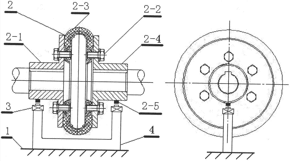
[0048] combined with Figure 5 And attached Figure 7 A non-contact dynamic torque, speed and shaft power sensor with two signal receivers is described based on the improved plum blossom flexible coupling. Firstly, make a relational chart of the static torque of the coupling and the relative displacement between the active half and the passive half, and input the relational table into the first data processor of the signal processing circuit as basic data. When the driving shaft rotates and drives the driven shaft to rotate through the flexible coupling, when the driven shaft is unloaded, the torque is zero (or close to zero), the relative displacement between the two coupling halves is zero, and the two signal receivers from The signal test points obtain fluctuating signals respectively, and the two signals are amplified, shaped and phase-compared by the s...


PUM


Abstract

The invention relates to measurement of rotation motive power of mechanical transmission as well as application of data thereof. According to the invention, an existing flexible coupler is utilized, and signal testing points are arranged on a driving half and a driven half of the flexible coupler respectively; through signal receivers arranged at the signal testing points on the two opposite coupling halves, relative positions of the driving half and the driven half during the rotation, as well as motion (rotating speed and rotating direction) signals thereof, can be obtained in a non-contact manner; and meanwhile, torque and rotating speed data can be obtained through a signal processing circuit, and the real-time shaft power of the mechanical transmission can be derived from the relation between the shaft power and the torque/the rotating speed. By the non-contact dynamic torque, rotating speed and shaft power signal transducer, the torque, the rotating speed and the shaft power in the mechanical transmission can be measured more simply and conveniently; the relevant equipment is simpler in structure, smaller in size, lighter in weight and lower in manufacture cost; the improvement of intelligentizing and lightening of the mechanical equipment is facilitated; the popularization of the intelligent mechanical equipment is facilitated; the optimization of the fit degree among the mechanical equipment is facilitated; the improvement of the mechanical transmission efficiency is facilitated; and the energy conservation and the emission reduction are facilitated.

Description

technical field [0001] The invention relates to the measurement of the rotational power of mechanical transmission and the application of the data. Background technique [0002] The measurement of torque, rotational speed and shaft power has a wide range of applications, and it penetrates into various fields such as industry, agriculture, transportation, aerospace, national defense, and energy. [0003] Torque, speed and shaft power are important working parameters of rotating power machinery and an important part of mechanical quantity measurement. If the average or instantaneous torque value, speed and power of the tested machinery can be measured accurately, reliably and conveniently, it will be beneficial to improve and improve the performance of mechanical equipment. At the same time, the device test system can be used as a monitoring device for the daily operation of rotating power machinery, for fault diagnosis or as a detection device for an automatic control system...

Claims


Application Information

Patent Timeline
Patent Type & Authority Applications(China)
IPC IPC(8): G01L3/24G01L3/04G01P3/00
Inventor 王建钧
Owner 王建钧
Why Eureka
Try Eureka