
Camping lamp

A technology of camping lights and light-emitting components, which is applied in lighting and heating equipment, portable lighting devices, with built-in batteries, etc., and can solve the problems of increasing the size of camping lights

Inactive Publication Date: 2012-11-21
OSRAM GMBH
View PDF0 Cites 1 Cited by
  • Summary
  • Abstract
  • Description
  • Claims
  • Application Information

AI Technical Summary

Problems solved by technology

This approach necessarily increases the size of the camping light, and as the number of light sources increases, so does the number of batteries that power them

Method used


Image

  • Camping lamp
  • Camping lamp
  • Camping lamp

Examples


Embodiment Construction

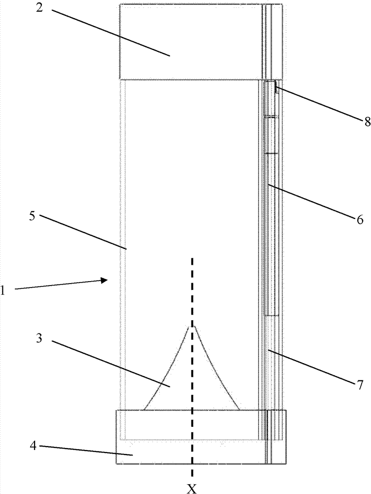
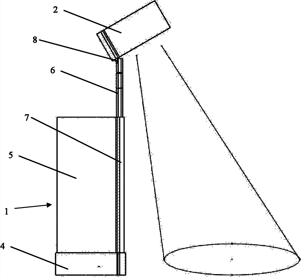
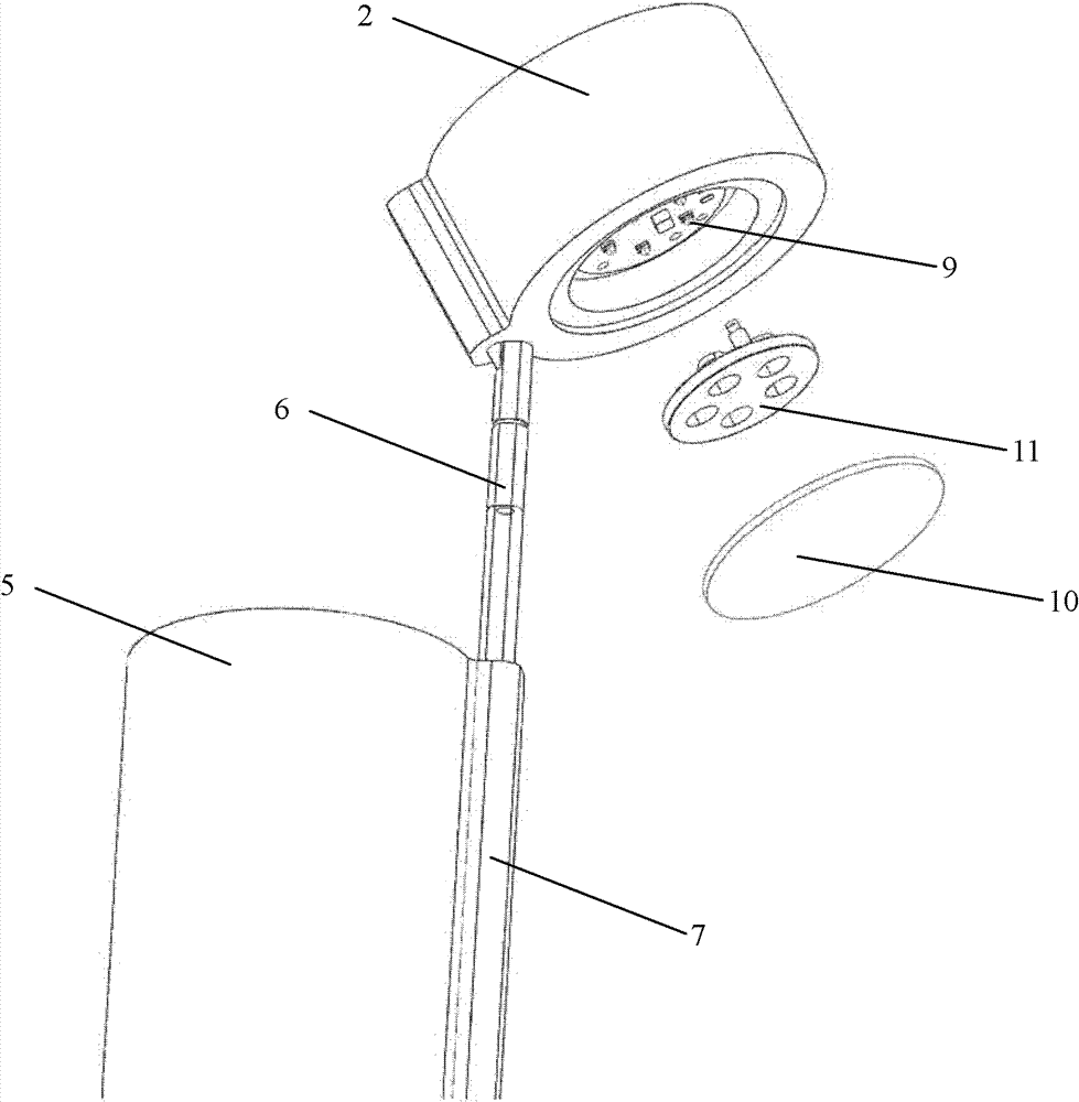
[0020] figure 1 A schematic diagram of a camping light according to the invention is shown in a conventional state. It can be seen from the figure that the camping light has: a bottom part 1, which includes a base 4 and a transparent cover 5 of astigmatism arranged on the base 4; There is at least one light source 9 (see image 3 ). A reflector 3 that reflects light from a light source 9 is provided in the transparent cover 5 . In this embodiment, the reflector 3 is designed in a conical shape, wherein the top of the conical reflector 3 points to the direction of the light-emitting assembly 2, and the conical surface of the reflective surface of the conical reflector 3 is formed as curved surface. In addition, the camping light also has a telescopic rod 6, which is telescopically accommodated in a telescopic rod receiving portion 7 formed in the transparent cover 5, and the telescopic rod 6 is hinged to the light-emitting assembly 2 with one end thereof using a universal j...


PUM


Abstract

The invention relates to a camping lamp which comprises a bottom portion (1) and a luminous component (2) arranged on the bottom portion (1). The camping lamp is characterized in that the luminous component (2) can move relative to the bottom portion (1) so that switch between a first state and a second state can be achieved, and the luminous component (2) provides a circumferential illumination in the first state and provides a perpendicular incidence illumination in the second state. Simultaneously, the camping lamp is small in size and easy to carry.

Description

technical field [0001] The invention relates to a camping lamp for field lighting. Background technique [0002] Camping is more and more popular and loved by people. People enjoy the tranquility and beauty of nature in camping, away from the hustle and bustle of life in the city, and relax in nature. When camping in the wild at night, camping lights are usually used for lighting. This camping light can provide conventional lighting to meet people's general needs, such as providing good and comfortable lighting for friends to chat together. However, when camping in the wild, it is often necessary to read and write. At this time, the lighting provided by the camping lamp cannot meet people's needs, because most of the light emitted by the camping lamp is useless, and the light that can be used is often too much Not enough to provide enough lighting for writing and reading. Of course, the requirement can be met by increasing the illumination intensity of the light source, su...

Claims


Application Information

Patent Timeline
IPC IPC(8): F21L4/00F21V19/02F21V7/04F21V17/00F21V21/22F21V13/00
Inventor 陈友黎安淼张奇辉明玉生
Owner OSRAM GMBH
Learn More