
Torque clutch and coal cutter

A technology for torque clutches and shearers, applied in clutches, automatic clutches, mechanical equipment, etc., can solve problems such as high cost and long torque shaft length, and achieve the effects of less consumables, small pull-out distance, and cost savings

Active Publication Date: 2012-11-21
SANY HEAVY EQUIP
View PDF9 Cites 8 Cited by
  • Summary
  • Abstract
  • Description
  • Claims
  • Application Information

AI Technical Summary

Problems solved by technology

This kind of torque clutch uses the motor shaft as the torque shaft to play the role of elastic buffer and overload protection. Once the torque shaft is twisted, it needs to be pulled out for a long distance to replace the new torque shaft, and the replacement torque shaft is longer. higher cost

Method used


Image

  • Torque clutch and coal cutter
  • Torque clutch and coal cutter
  • Torque clutch and coal cutter

Examples


Embodiment Construction

[0026] It should be noted that, in the case of no conflict, the embodiments of the present invention and the features in the embodiments can be combined with each other. The present invention will be described in detail below with reference to the accompanying drawings and examples.

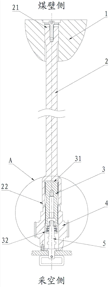
[0027] image 3 and Figure 4 It is a related drawing of the embodiment of the present invention, as shown in the figure, the torque clutch described in this embodiment includes a motor shaft 2 and a torque shaft 3, and the first end 21 of the motor shaft is installed on the hollow shaft motor 1 Inside, the second end 22 of the motor shaft is coaxially splined with the first end 31 of the torque shaft, and the second end 32 of the torque shaft is connected with the transmission gear 4 with a coaxial spline. Both ends are external splines, and the second end 32 of the torque shaft is connected with a pull rod 5 protruding from the end of the transmission gear 4, through which the pull rod 5 oper...


PUM


Abstract

The invention provides a torque clutch and a coal cutter. One end of the torque clutch is installed in a hollow shaft motor while the other of the torque clutch is connected with a transmission gear. The torque clutch comprises a motor shaft and a torque shaft. Both ends of the motor shaft and the torque shaft are respectively a first end and a second end. The first end of the motor shaft is installed in the hollow shaft motor and the second end of the motor shaft is coaxially connected with the first end of the torque shaft. The second end of the torque shaft is coaxially connected with the transmission gear. A pull rod extending out of the end part of the transmission gear is connected at the second end of the torque shaft. According to the torque clutch provided by the invention, aiming at a cutting part in C-shaped layout, the torque shaft clutch can be operated on a worked-out side, and as the motor shaft is longer, elastic deformation can be realized to realize the function of elastic buffer. As the torque shaft is provided with a groove structure or an arc-shaped gap, the function of overload protection can be realized.

Description

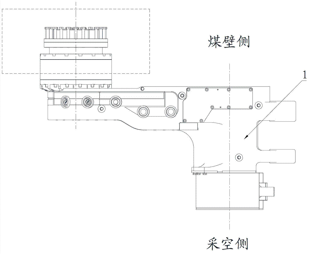
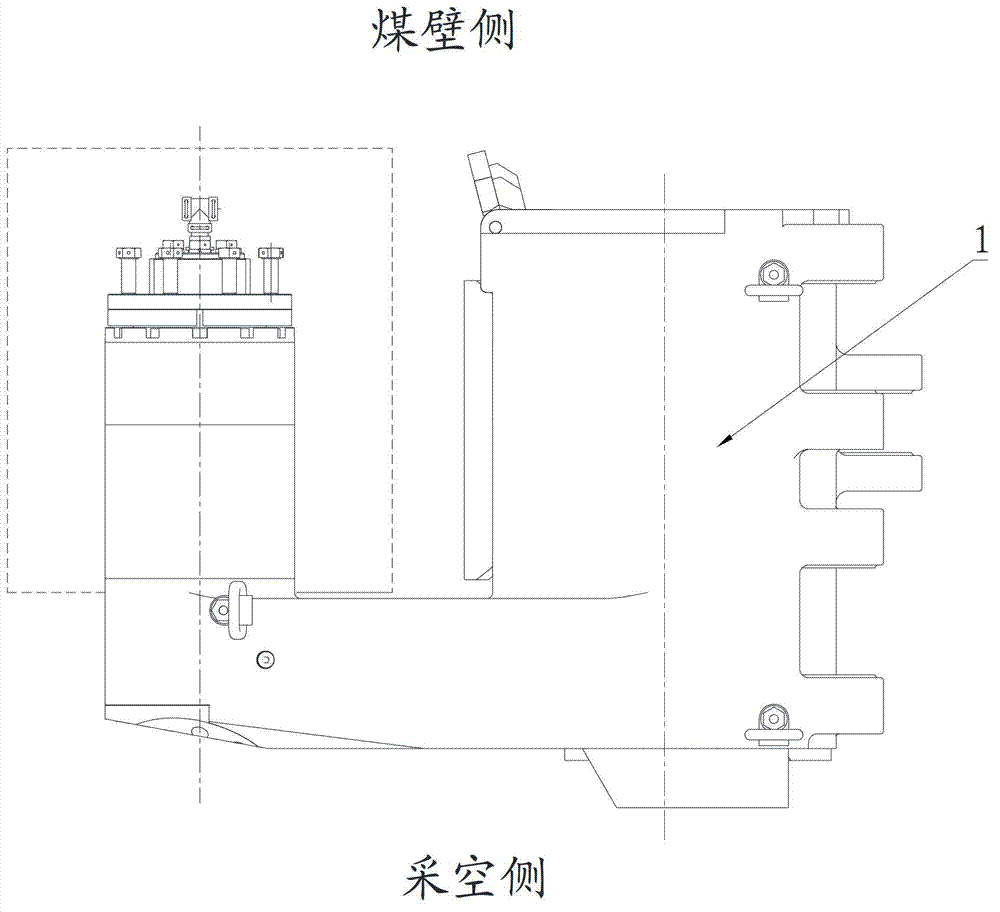
technical field [0001] The invention relates to the field of engineering machinery, in particular to a torque clutch and a coal shearer. Background technique [0002] The cutting part of the existing shearer is usually S-shaped layout (such as figure 1 As shown), the transmission gear is on the coal wall side, the motor shaft of the empty shaft motor 1 is on the goaf side, and its torque clutch is usually operated on the gob side. This kind of torque clutch uses the motor shaft as the torque shaft to play the role of elastic buffer and overload protection. Once the torque shaft is twisted, it needs to be pulled out for a long distance to replace the new torque shaft, and the replacement torque shaft is longer. higher cost. [0003] cut section for C-layout (eg figure 2 As shown), due to the change of the arrangement direction of the empty shaft motor 1, the motor shaft is on the side of the coal wall, and the transmission gear is on the gob side, so a convenient, safe an...

Claims


Application Information

Patent Timeline
Patent Type & Authority Applications(China)
IPC IPC(8): F16D43/20
Inventor 戴玉龙贾安鹏刘胜宏
Owner SANY HEAVY EQUIP
Learn More