Engine fan

An engine and fan technology, applied in the direction of machines/engines, liquid fuel engines, mechanical equipment, etc., can solve the problems of engine power consumption and fan weight increase

Inactive Publication Date: 2015-04-01
南充工塑零部件有限公司
View PDF7 Cites 0 Cited by
  • Summary
  • Abstract
  • Description
  • Claims
  • Application Information

AI Technical Summary

Problems solved by technology

There are also those that do not connect the blades with the hub, such as the Chinese invention patent, the application number is 01143024.9, and the name is a vehicle engine fan. The fan includes a supporting plate and blades. , the shank of the blade is sandwiched between two supporting plates, and an intermediate liner is fixed between the front and rear supporting plates. This structure increases the weight of the fan and consumes more engine power. Therefore, a practical engine fan is known by the public. what you want

Method used


Image

  • Engine fan
  • Engine fan
  • Engine fan

Examples


Embodiment Construction

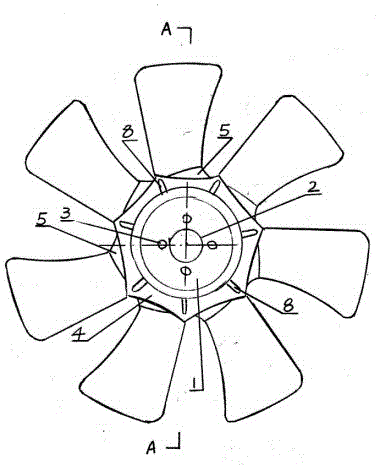
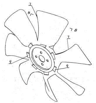
[0011] Such as figure 1 As shown, the fan includes a disc 1 in the center, with a central hole 2, and a group of small holes 3 evenly distributed around the hole. Edges are formed on the periphery, except that the edge wraps a part of the disc 1 to form a convex edge, and extends outward to form a plastic ring 4 with a width. The blades are unevenly distributed on the periphery of the plastic ring. Seven blades are distributed in this embodiment. The above-mentioned uneven distribution means that the included angles between each adjacent two blades are different, forming unequal fan gaps. According to experiments, it can reduce the vibration of the fan. The uneven distribution of this embodiment is manifested in the scale The angle is between 43°-55°.

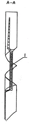
[0012] The width of each blade on the edge of the plastic ring forms the root of the fan blade according to the width obtained by graduation. The curve of the root of the fan blade is twisted at an angle along the plane of the...


PUM


Abstract

The invention discloses an engine fan, which includes a metal disc (1) connected with the transmission shaft of an engine, wherein a plastic ring (4) is formed on the edge of the round disc through injection molding and wrapping; seven to ten blades are non-uniformly distributed on the circumference of the plastic ring, the angles of the blades are variably twisted corresponding to the rotary center of the round disc, the root parts and the chain edges of the blades are connected through strength structures, the areas of the blades are gradually enlarged from inside to outside, and the cross sections thereof are gradually lessened from inside to outside. The engine fan overcomes the defect of the conventional fan that the heat dissipation is not possible as the air can't enter the center of the hub, and removes the air intake dead angle; and the root parts of the blades are structurally strengthened, the air intake amount is increased, and the weight is reduced for one third.

Description

technical field [0001] The invention relates to an engine, in particular to a fan installed in an automobile engine. Background technique [0002] Usually the engine needs to be air-cooled to cool down. Generally, a fan is installed at the front end of the engine, but the working environment of the fan is very harsh, with high temperature and vibration. In order to improve the strength of the fan, the known fan has a ring-shaped hub near the center. The hub supports the root of the blade and is connected to the transmission system. The twist angle, so the hub has a certain width, but in this way, when the fan rotates, the center does not enter the air, so the heat cannot be dissipated. The traditional fan blades are evenly distributed, the area of ​​the blades is the same, and the cross-section of the blades is uniform. There are also those that do not connect the blades with the hub, such as the Chinese invention patent, the application number is 01143024.9, and the name i...

Claims


Application Information

Patent Timeline
Patent Type & Authority Patents(China)
IPC IPC(8): F04D29/32F04D29/38
CPCF04D29/329
Inventor 邓昌立杜万才王志友黄玉吉
Owner 南充工塑零部件有限公司
Why Eureka
Try Eureka