an electric shower
A shower and electric technology, applied in the direction of spraying devices, brushes, household appliances, etc., can solve the problems of water flowing far away from the human body, single function, poor cleaning effect, etc., to achieve the adjustment of excitement, high cleaning efficiency, and good cleaning effect Effect
- Summary
- Abstract
- Description
- Claims
- Application Information
AI Technical Summary
Problems solved by technology
Method used
Image

Examples
Embodiment 1
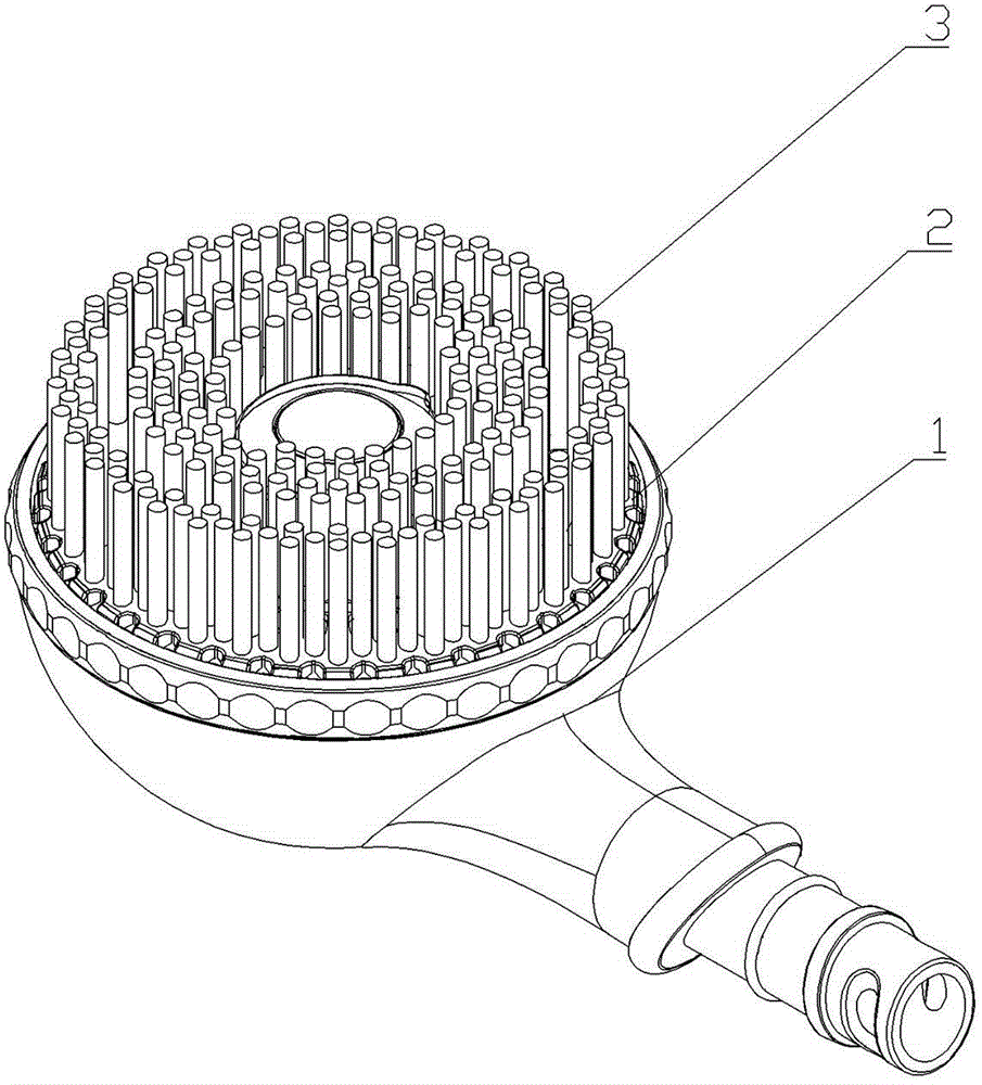
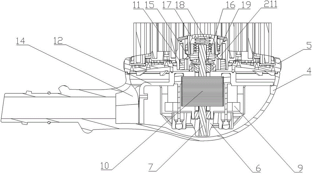
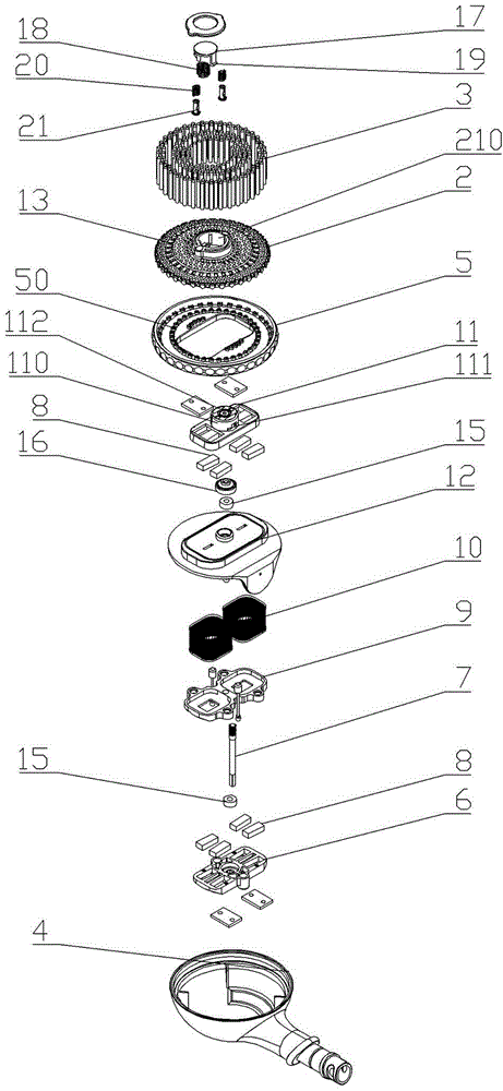
[0027] Such as figure 2 , image 3 As shown, this embodiment includes a shower body 1, a rotating brush 2 rotatably arranged on the shower body 1, and a transmission device connected to the rotating brush 2 arranged on the shower body 1. The shower body 1 includes a brush head rear cover 4 and a brush head front cover 5 compatible with the brush head rear cover 4. The lower rotating disk 6, the transmission shaft 7, the magnetic steel 8, the coil fixing frame 9, the induction coil group 10 and the upper rotating disk 11 above the sealing cover 12, the rotating brush 2 is located on the brush head front cover 5 Above, the bristles 3 are fixedly arranged on the rotating brush 2, and a water outlet hole 13 is provided on the rotating brush 2 at a position staggered from the bristles 3, and the shower body 1 is located in the cavity of the shower body 1 The outside of the sealing cover 12 is a water flow channel 14, the brush head front cover 5 is provided with a through hole 5...
Embodiment 2
[0031] Such as Figure 4 As shown, this embodiment is substantially the same as Embodiment 1, the difference is that the transmission device of the present invention includes a motor 22 and a rotating body 23 sealed in the cavity of the shower body 1 through the sealing cover 12 , curved rod 24 and the transmission shaft 7, the motor 22 is vertically fixed on the bottom wall of the brush head rear cover 4, and the upper end of the transmission shaft 7 passes through the sealing cover 12, the brush The head front cover 5 is threadedly connected with the upper rotating disc 11 behind, and the lower end is threadedly connected with the rotating body 23. The transmission shaft 7 is rotatably matched with the sealing cover 12 through the bearing 15, and on the rotating shaft 7 A waterproof sealing ring 16 is arranged above the contact with the sealing cover 12 to seal the transmission shaft 7, the lower end of the curved rod 24 is fixed on the rotating shaft of the motor 22, and th...
Embodiment 3
[0033] Such as Figure 5 As shown, this embodiment is substantially the same as Embodiment 2, the difference is that the transmission device in this embodiment also includes a gear set in the space sealed by the sealing cover 12, and the gear set is respectively connected to the curved rod 24 is connected to the rotating shaft of the motor 22, specifically, the gear set includes a driving gear 25 and a driven gear 26, the driving gear 25 is meshed with the driven gear 26, and the driving gear 25 is engaged with the driven gear 26. The gear 25 is fixedly arranged on the rotating shaft of the motor 22, the driven gear 26 is fixedly connected with the lower end of the bent rod 24, and the driven gear 26 passes through the motor fixing cover and the gear arranged on the motor fixing cover. The fixed frame is rotationally matched, that is, the driven gear 26 is rotatable, and the setting of the gear set mainly plays the role of speed regulation.
PUM
 Abstract
Description
Claims
Application Information
 - R&D
- Intellectual Property
- Life Sciences
- Materials
- Tech Scout
- Unparalleled Data Quality
- Higher Quality Content
- 60% Fewer Hallucinations
Browse by: Latest US Patents, China's latest patents, Technical Efficacy Thesaurus, Application Domain, Technology Topic, Popular Technical Reports.
© 2025 PatSnap. All rights reserved.Legal|Privacy policy|Modern Slavery Act Transparency Statement|Sitemap|About US| Contact US: help@patsnap.com