Method for manufacturing a laminate with one metal-plated side
A technology of metal coating layer and manufacturing method, which is applied in the direction of metal layered products, printed circuit manufacturing, chemical instruments and methods, etc., can solve the problems of rapid deterioration of protective materials, gaps between layers, and increased manufacturing costs, so as to improve industrial Excellent production efficiency, excellent interlayer adhesion, and excellent reliability
- Summary
- Abstract
- Description
- Claims
- Application Information
AI Technical Summary
Problems solved by technology
Method used
Image
Examples
Embodiment 1
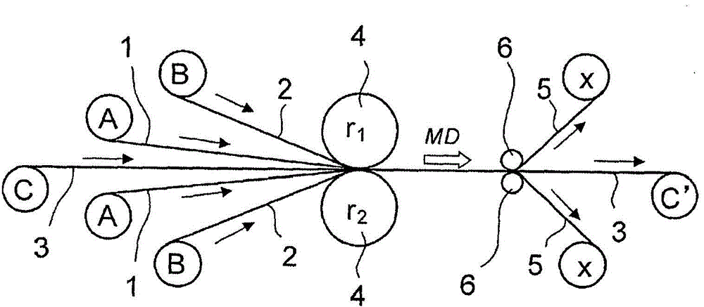
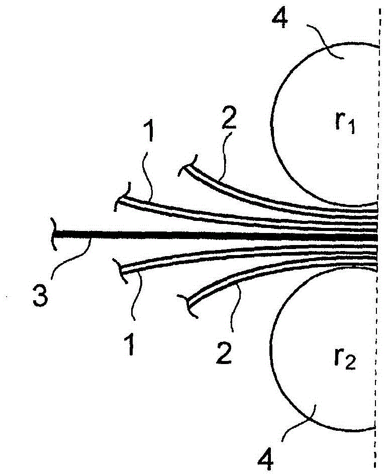
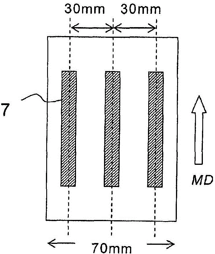
[0062] As the insulating film (A), prepare a liquid crystal polymer film 1 (melting point 320° C.) with a thickness of 50 μm and a width of 70 mm rolled into a roll-shaped long film. Commercially available electrolytic copper foil 2 (surface roughness Rz: insulating film lamination surface 1.6 μm, exposed surface 1.4 μm) was rolled into a roll-shaped long copper foil, and an aluminum foil with a thickness of 50 μm and a width of 70 mm was prepared as a separator (C). 3 (front and back surface roughness Rz: both 1.2 μm) was rolled into a roll-shaped long aluminum foil. put these as figure 1 As shown, they are respectively installed on the insulating film conveying roller A, the metal foil conveying roller B, and the spacer film conveying roller C, on a pair of pressure rollers 4 (r 1 、r 2 ), are supplied so as to overlap in the order of "electrodeposited copper foil 2 / liquid crystal polymer film 1 / aluminum foil 3 / liquid crystal polymer film 1 / electrodeposited copper foil 2" (...
Embodiment 2
[0066] A non-thermoplastic commercially available heat-resistant polyimide film 3 (Tg: 340° C., surface roughness of both front and back: 0.9 μm) with a thickness of 50 μm was used as the separator (C), and the In Example 1, a single-sided copper-clad laminate according to Example 2 was obtained in the same manner.
[0067] In this Example 2, the delamination of the liquid crystal polymer film 1 and the heat-resistant polyimide film 3 after thermocompression bonding was not defective and proceeded very smoothly. As a result, no cracks, wrinkles, or surface roughness were observed on the front and back surfaces of the copper laminate 5 . In addition, in the measurement using the peelability test piece, 0.07 kN / m of interface peeling was confirmed. In addition, in the evaluation using the adhesion test piece, the [adhesion] was good, and the [unevenness in adhesion] was 0.02 kN / m, and it was confirmed that the liquid crystal polymer 1 and the electrodeposited copper foil 2 were...
Embodiment 3
[0069] As the spacer film (C), a double-sided copper-clad laminate (manufactured by Nippon Steel Chemical Co., Ltd., Espanex M series (MB12-25-12CEG)) was used, and the film related to Example 3 was obtained in the same manner as in Example 1. Copper clad laminate on one side. This double-sided copper-clad laminate has a polyimide resin with a thickness of 25 μm as an insulating layer in the center, and copper foils with a thickness of 12 μm are provided on both sides, and the surface roughness (Rz) of the exposed surfaces of the copper foils is 1.0. μm.
[0070] In the production of Example 3, the interlayer delamination between the liquid crystal polymer film 1 and the heat-resistant polyimide film 3 after thermocompression bonding was not defective and proceeded very smoothly. As a result of covering the front and back surfaces of the copper laminate 5 , no cracks, wrinkles, or surface roughness were observed at all. In addition, in the measurement using the peelability t...
PUM
| Property | Measurement | Unit |
|---|---|---|
| surface roughness | aaaaa | aaaaa |
| thickness | aaaaa | aaaaa |
| thickness | aaaaa | aaaaa |
Abstract
Description
Claims
Application Information
 - Generate Ideas
- Intellectual Property
- Life Sciences
- Materials
- Tech Scout
- Unparalleled Data Quality
- Higher Quality Content
- 60% Fewer Hallucinations
Browse by: Latest US Patents, China's latest patents, Technical Efficacy Thesaurus, Application Domain, Technology Topic, Popular Technical Reports.
© 2025 PatSnap. All rights reserved.Legal|Privacy policy|Modern Slavery Act Transparency Statement|Sitemap|About US| Contact US: help@patsnap.com


