
Neon lamp indicator lamp

A technology of indicator lights and neon lamps, applied in the field of lighting design, can solve the problems of short life, inconspicuousness, and high power consumption, and achieve the effects of long life, good heat dissipation, and low power consumption

Inactive Publication Date: 2012-11-14
DALIAN LUFEI PHOTOELECTRIC TECH
View PDF0 Cites 2 Cited by
  • Summary
  • Abstract
  • Description
  • Claims
  • Application Information

AI Technical Summary

Problems solved by technology

[0002] The neon lamps currently used in the market often have problems such as inconspicuousness, high power consumption, poor heat dissipation, and short life due to the continuous operation of the neon lamps.

Method used


Image

  • Neon lamp indicator lamp

Examples


Embodiment Construction

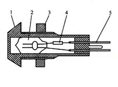
[0009] Such as figure 1 As shown, the present invention includes a lampshade 1, a neon lamp 2, a current-limiting resistor 4, and a pin 5. The neon lamp 5 is installed inside the lampshade 1, and the neon lamp 2 is connected to the pin 5. The lampshade 1 extends inside, and a current-limiting resistor 4 is installed between the pin 5 and the neon lamp 2. The outer surface of the lampshade 1 is machined with threads, and a nut 3 is installed through the threads, so that the lampshade 1 and the neon lamp are tightly fixed. The structure is more compact.

[0010] The above are only the preferred specific embodiments of the present invention, but the protection scope of the present invention is not limited to this. Anyone familiar with the technical field within the technical scope disclosed in the present invention, according to the technical solution of the present invention Equivalent replacements or changes to its inventive concept should all fall within the protection scope of ...


PUM


Abstract

The invention discloses a neon lamp indicator lamp which comprises a lampshade, a neon lamp, a current-limiting resistor and a lead pin. The neon lamp is installed inside the lampshade and connected with the lead pin, the lead pin extends out of the lampshade, and the current-limiting resistor is installed between the lead pin and the neon lamp. The neon lamp indicator lamp has the advantages of being simple and compact in structure, good in indicating performance, little in power consumption, good in heat dissipation and long in service life.

Description

Technical field [0001] The invention relates to the field of lamp design, in particular to a neon lamp indicator. Background technique [0002] The indicator neon lamps currently on the market often have problems such as unobtrusiveness, high power consumption, poor heat dissipation, and short life due to the continuous operation of the neon lamps. Summary of the invention [0003] The purpose of the present invention is to overcome the above-mentioned shortcomings and provide a neon lamp indicator. [0004] The technical solution adopted by the present invention to achieve the above-mentioned object is: a neon lamp indicator light, including a lamp shade, a neon lamp, a current limiting resistor, and a pin. The neon lamp is installed inside the lamp shade, and the neon lamp is connected to the pin. The pin extends from the lampshade, and a current limiting resistor is installed between the pin and the neon lamp. [0005] The outer surface of the lampshade is machined with threads, ...

Claims


Application Information

Patent Timeline
Patent Type & Authority Applications(China)
IPC IPC(8): F21S8/00F21V23/02F21V17/12
Inventor 赵德喜徐旭东
Owner DALIAN LUFEI PHOTOELECTRIC TECH
Learn More