Wind blocking board in heat preservation box

A technology for a thermal insulation box and a windshield, which is applied in the field of windshields, can solve the problems of large thread swaying, high waste thread consumption, and many broken ends, etc. Solve the effect of broken heads

Active Publication Date: 2012-11-14
张家港欣欣高纤股份有限公司
View PDF12 Cites 1 Cited by
  • Summary
  • Abstract
  • Description
  • Claims
  • Application Information

AI Technical Summary

Problems solved by technology

During spinning, the tow runs on the hot roller at high speed and rubs against the air, resulting in greater air resistance. The air in the insulation box is discharged from the exhaust pipe, causing the tow to vibrate violently on the hot roller. Due to the currently used The windshield, the original strip-shaped windshield, forms an angle of 35-45° with the right side of the lower bottom of the trapezoid and moves inward along this angle to a distance of 40mm from the apex of the lower right corner. The windshield effect is poor, so During high-speed winding, the filaments on the hot roller vibrate a lot, especially the silk path on the outermost ring of the hot roller shakes very violently, resulting in many broken ends, high waste filament consumption, low quality product rate, and low production efficiency. Many problems such as high cost, increased unevenness of finished silk, decreased dyeing, etc.

Method used


Image

  • Wind blocking board in heat preservation box
  • Wind blocking board in heat preservation box

Examples


Embodiment Construction

[0010] The windshield in the thermal insulation box of the present invention will be further described in detail below through specific examples.

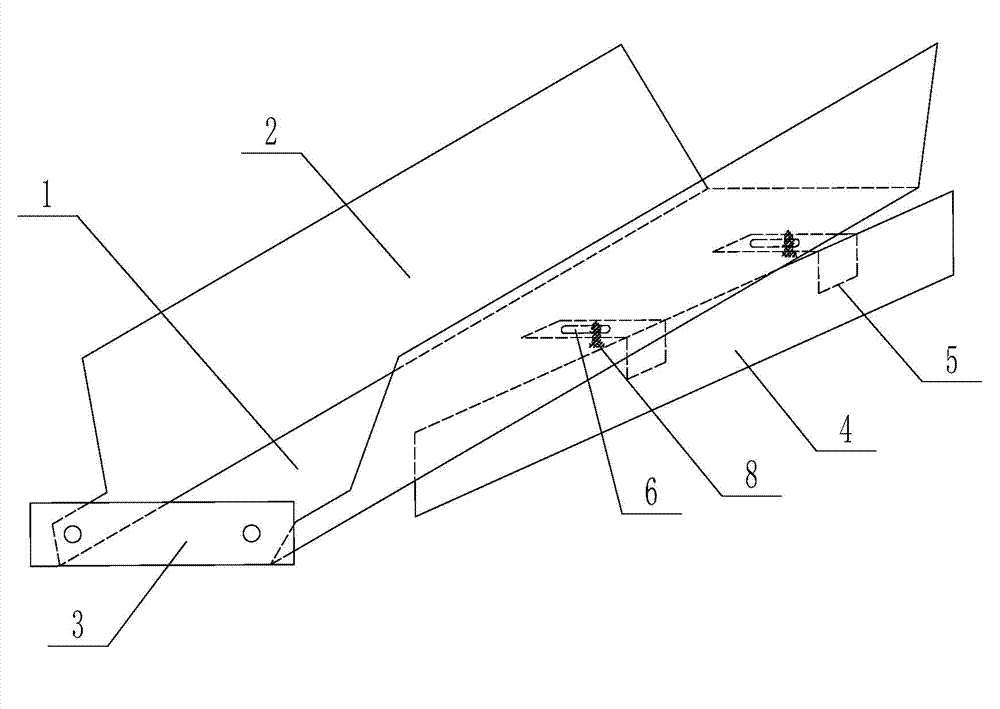
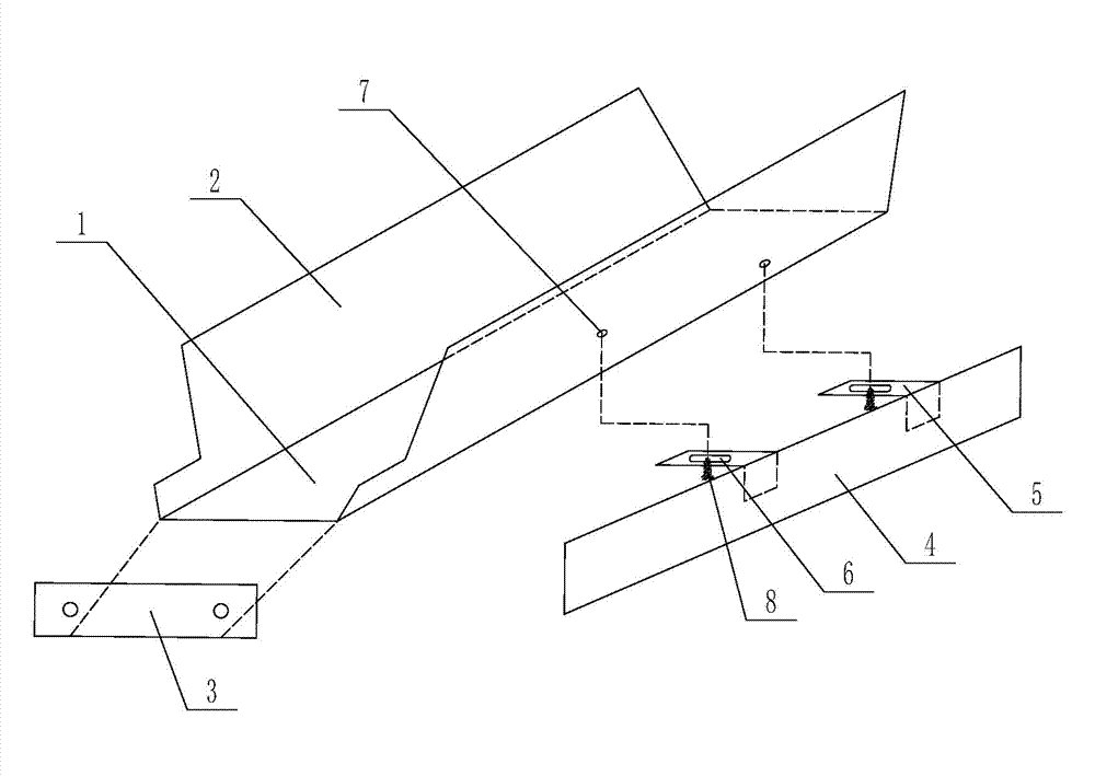
[0011] Such as figure 1 , figure 2 As shown, the windshield in the heat preservation box includes a trapezoidal body with a wide top and a narrow bottom made of a bottom plate 1 and two outwardly inclined side plates 2. A connecting plate 3 is provided on the left side of the bottom plate 1. The included angle between the side plates 2 and the bottom plate 1 is between 125° and 135°, and the lower part of the bottom plate 1 is provided with a strip-shaped air distribution plate 4, which is vertically arranged with the bottom plate 1, and the air distribution plate 4 The included angle with the right end face of the trapezoid is between 55° and 75°.

[0012] The connection structure between the air distribution plate 4 and the bottom plate 1 is: the side of the air distribution plate 4 is fixed with an adjustment plate 5, the adj...


PUM


Abstract

The invention relates to a wind blocking board in a heat preservation box. The wind blocking board comprises a trapezoid body with big top and small bottom, wherein the trapezoid body is formed by a bottom board and two lateral boards inclining outwards. A connection board is arranged on the left side of the bottom board, an included angle formed by each lateral board and the bottom board ranges from 125 degrees to 135 degrees, a long strip-shaped wind distribution board is arranged at the lower portion of the bottom board and is perpendicular to the bottom board, and an included angle formed by the wind distribution board and the trapezoid body ranges from 55 degrees to 75 degrees. The wind blocking board is suitable for being used in the heat preservation box for producing chemical fiber dacron fully-drawn yarns (FDY).

Description

technical field [0001] The invention relates to the field of chemical fiber spinning equipment, in particular to a windshield in an insulated box. Background technique [0002] The windshield is used in the insulation box produced by chemical fiber FDY polyester drawn yarn. There is a ¢90mm exhaust pipe on the upper right of the insulation box. There is also a root heat roller and a roller in the middle of the box. The trapezoidal windshield is set under the heat roller. The windshield currently used is usually a It is a trapezoidal structure with openings on the upper part and both sides, wide at the top and narrow at the bottom. A connecting plate is set on one side of the trapezoid to connect with the heat preservation box. Wind board left. During spinning, the tow runs on the hot roller at high speed and rubs against the air, resulting in greater air resistance. The air in the insulation box is discharged from the exhaust pipe, causing the tow to vibrate violently on t...

Claims


Application Information

Patent Timeline
Patent Type & Authority Applications(China)
IPC IPC(8): D01D13/02D01D10/02
Inventor 贲永宝
Owner 张家港欣欣高纤股份有限公司
Why Eureka
Try Eureka