
Safe and automatic hydraulic control opening and closing valve and infusion apparatus with safe and automatic hydraulic control opening and closing valve

A safe and automatic opening and closing valve technology, applied in the field of infusion sets, can solve the problems of difficult processing, difficult to achieve automatic liquid stop effect, and unsatisfactory sealing effect

Inactive Publication Date: 2012-11-14
戴建达
View PDF9 Cites 19 Cited by
  • Summary
  • Abstract
  • Description
  • Claims
  • Application Information

AI Technical Summary

Problems solved by technology

[0007] At present, the sealing mechanism used for automatic liquid stop is nothing more than the above three solutions, one is to use a spherical seal at the lower end of the floating body to fit closely with the bottom of the drip funnel and then block the liquid outlet to stop the liquid; the other One is to set a stopper at the lower end of the floating body, and when the floating body falls by its own weight, block the liquid outlet at the bottom of the dropping funnel to stop the liquid; the last one is to completely cover the liquid outlet pipe with the water stop to realize the liquid stop; however, In the actual application process, it is found that these three methods have defects, the processing is not easy, or the sealing effect is not ideal in practice, and it is difficult to achieve a better automatic liquid stop effect

Method used


Image

  • Safe and automatic hydraulic control opening and closing valve and infusion apparatus with safe and automatic hydraulic control opening and closing valve
  • Safe and automatic hydraulic control opening and closing valve and infusion apparatus with safe and automatic hydraulic control opening and closing valve
  • Safe and automatic hydraulic control opening and closing valve and infusion apparatus with safe and automatic hydraulic control opening and closing valve

Examples


no. 1 example

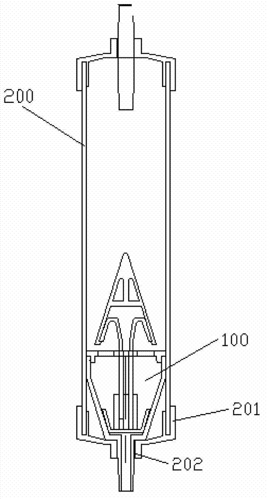
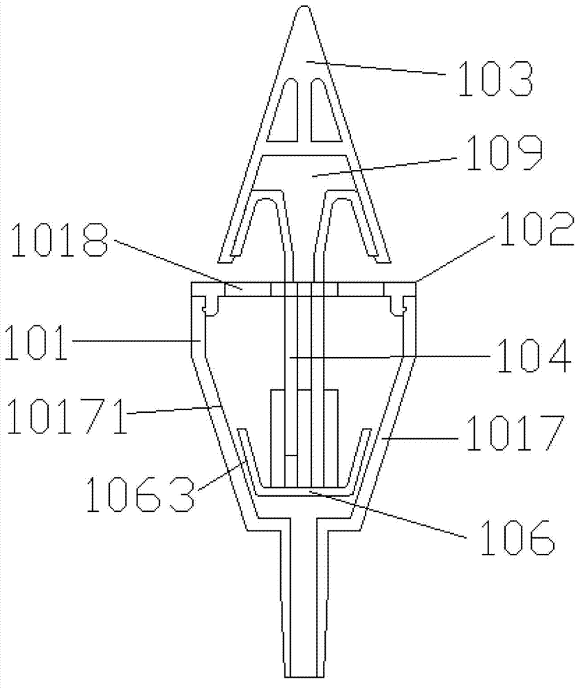
[0070] refer to Figure 1a to Figure 6 , the present embodiment provides a safety automatic hydraulic control opening and closing valve 100 as shown in FIG. , the upper floating body 103 and the sealing body 106; the valve body 101 includes a truncated cone section 1017, and the liquid outlet hole 1018 on the valve body is plugged and connected with the liquid outlet hole 202 in the dropping funnel 200; as Figure 4a The central position of the valve cover 102 shown is provided with a through hole 1021 through which the floating body connecting rod 104 passes, and the valve cover 102 is buckled on the valve body 101; the upper floating body 103 and the sealing body 106 are connected through the hollow floating body connecting rod 104 , the upper floating body 103 is placed outside the valve body 101; the sealing body 106 is in the shape of a frustum of a cone and placed inside the valve body 101; The inclined surface 10171 of 1017 contacts to realize sealing.

[0071] prefer...

no. 2 example

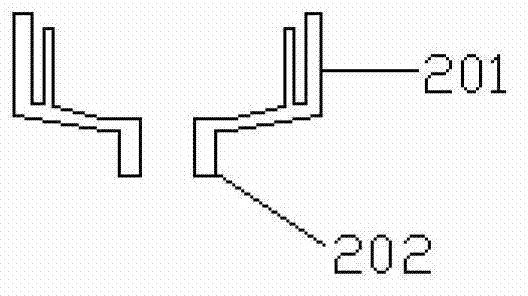
[0083] refer to Figure 3 to Figure 14b , this example provides Figure 7 A safety automatic hydraulic control opening and closing valve 100 is shown, the safety automatic hydraulic control opening and closing valve 100 is placed in the drip funnel 200, which includes: a valve body 101, a valve cover 102, a lower floating body 105, an upper floating body 103 and a sealing body 106; the valve body 101 is plugged into the liquid outlet hole 202 on the bottom shell 201 of the dripping funnel 200 (some icons are not shown);

[0084] Such as Figure 7 The valve cover 102 shown is fastened on the valve body 101; the lower floating body 105 is placed in the valve body 101; the upper floating body 103 and the lower floating body 105 are connected by a hollow floating body connecting rod 104 and placed outside the valve body 101; the sealing body 106 The sealing body connecting rod 107 is connected to the bottom of the lower floating body 105; the sealing body 106 realizes sealing by...

no. 3 example

[0098] refer to Figure 15 to Figure 22 , this example provides Figure 15 A kind of safety automatic hydraulic control opening and closing valve 100 shown, as Figure 16 The shown safety automatic hydraulic control opening and closing valve 100 is placed in the dropping funnel 200, including: a valve body 101, a valve cover 102, an upper floating body 103, a lower floating body 105 and a sealing body 106; Figure 17a The valve body 101 shown includes an upper column section 1011, a middle cone section 1012 and a lower insertion section 1013; refer to Figure 17b and Figure 17c The inner cavity of the shown middle cone section 1012 is conical, and the outer circumference is pyramidal, such as Figure 17a Between the shown upper column section 1011 and the middle cone section 1012, an inner boss 1015 and an outer boss 1016 extending to the inside and outside of the valve body 101 are provided. The middle cone section 1012 is provided with four evenly distributed through ho...


PUM


Abstract

The invention discloses a safe and automatic hydraulic control opening and closing valve, which is arranged in a dropping funnel. The safe and automatic hydraulic control opening and closing valve is characterized by comprising a valve body, a valve cover, an upper floating body and a sealing body, wherein the valve body comprises a frustum section; a liquid outlet hole on the valve body is fixedly connected with the liquid outlet hole in the dropping funnel; a through hole through which a floating body connection rod passes is arranged at the center position of the valve cover; the valve cover is locked on the valve body; the upper floating body is connected with the sealing body through a hollow floating body connection rod; the upper floating body is arranged outside the valve body; the sealing body forms a frustum shape and is arranged in the valve body, and the sealing surface on the sealing body and an inclined plane on the frustum section of the valve body are in contact to be sealed. The automatic hydraulic control opening and closing valve disclosed by the invention has good stopping effect, can conveniently release stopping, and can be continuously used.

Description

technical field [0001] The invention relates to a medical device for intravenous infusion for clinical patients, specifically a safe automatic hydraulic control opening and closing valve and an infusion set with the safe automatic hydraulic control opening and closing valve Background technique [0002] When carrying out intravenous infusion to patient at present, widely use disposable infusion set, mainly by bottle stopper piercer, air inlet device, dropping funnel, flow regulator, medicinal liquid filter, venous infusion needle and some connecting conduits. Under the action of atmospheric pressure, the liquid in the bottle flows into the drip funnel along the thinner infusion hose, and when the water column pressure in the drip funnel is greater than the venous pressure, the liquid in the bottle flows into the vein along the hose. During the infusion process, the attendant needs to pay close attention to the liquid level of the liquid medicine. Otherwise, when the liquid l...

Claims


Application Information

Patent Timeline
Patent Type & Authority Applications(China)
IPC IPC(8): A61M5/40
Inventor 戴建达
Owner 戴建达
Learn More