Heat sink plate of switchgear and switchgear thereof

A switching device and heat sink technology, applied in electrical switches, electrical components, circuits, etc., can solve problems such as damage to circuits, and achieve the effect of speeding up the extinguishing speed and improving the heat dissipation capacity.

Inactive Publication Date: 2015-12-16
SIEMENS AG
View PDF6 Cites 0 Cited by
  • Summary
  • Abstract
  • Description
  • Claims
  • Application Information

AI Technical Summary

Problems solved by technology

[0003] When the switch device is turned off, due to the high temperature, both the fixed electric contact piece and the movable electric contact piece excite conductive particles, and an arc is generated between the fixed electric contact piece and the movable electric contact piece, so that the current passing through the switchgear increases to the rated value. More than ten times the current, if the heat cannot be dissipated immediately and the arc is extinguished, the huge heat generated by the current will seriously damage the entire circuit inside the switchgear

Method used


Image

  • Heat sink plate of switchgear and switchgear thereof
  • Heat sink plate of switchgear and switchgear thereof
  • Heat sink plate of switchgear and switchgear thereof

Examples


Embodiment Construction

[0038] In order to have a clearer understanding of the technical features, purposes and effects of the invention, the specific implementation manners of the present invention will now be described with reference to the accompanying drawings, in which the same reference numerals represent the same parts. In the drawings showing the respective embodiments, the same numerals denote components with the same structure or similar structures but with the same functions.

[0039] In order to make the drawing concise, the parts related to the present invention are only schematically shown in each drawing, and they do not represent the actual structure of the product. In addition, to make the drawings concise and easy to understand, in some drawings, only one of the components having the same structure or function is schematically shown, or only one of them is marked.

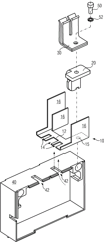
[0040] figure 1 It is an exploded schematic diagram of a three-dimensional structure of a schematic embodiment of a s...


PUM


Abstract

The invention provides a switching device radiating plate (10) which comprises a body (12) and a radiating portion (16). The body can be mounted on a shell (40) of a switching device, and a heat conducting port (14) corresponding to a radiating port (42) on the shell is arranged on the body. The radiating portion (16) is further arranged on the body and comprises a plurality of wings extending along the radiating direction capable of reducing the temperature in the shell. The invention further provides a switching device comprising the radiating plate. The radiating capacity of the switching device is improved, and electric arc generated in the shell can be extinguished.

Description

technical field [0001] The invention relates to a heat dissipation plate, in particular to a heat dissipation plate used for a switchgear, and also relates to a switchgear using the heat dissipation plate. Background technique [0002] The switchgear usually includes a circuit breaker, the housing of the circuit breaker is provided with a fixed electric contact piece, the electric contact piece is provided with a support member, and a fuse may be provided between the two support members. In the process of use, when the switchgear is in the open state, the current flows from one electric contact through the support and the fuse to the other electric contact. Due to a certain rated current, the safety bracket and fuse seal of the switchgear A certain amount of heat is generated at the cover, the fuse box and the circuit joint, especially for a switchgear passing a large rated current (such as 800A, 1250A, etc.), which seriously affects the reliability of the switchgear. Exist...

Claims


Application Information

Patent Timeline
Patent Type & Authority Patents(China)
IPC IPC(8): H01H9/52
Inventor 李翔王研波姜晓军刘云段新高方晓兰黄静吕远宋健康
Owner SIEMENS AG
Why Eureka
Try Eureka