
Regenerative heat exchanger with forced rotor seal

A technology for regenerating heat exchangers and seals, which is applied in the direction of regenerative heat exchangers, indirect heat exchangers, and engine sealing, which can solve the problems of expensive and complicated sealing systems, and is beneficial to installation and reduces sealing gas The effect of high volume, simple operation and maintenance

Inactive Publication Date: 2012-11-07
BALCKE DURR AG
View PDF7 Cites 0 Cited by
  • Summary
  • Abstract
  • Description
  • Claims
  • Application Information

AI Technical Summary

Problems solved by technology

Prior known sealing systems are often very complex and expensive in practice

Method used


Image

  • Regenerative heat exchanger with forced rotor seal
  • Regenerative heat exchanger with forced rotor seal
  • Regenerative heat exchanger with forced rotor seal

Examples


Embodiment Construction

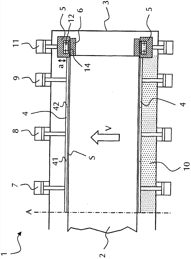
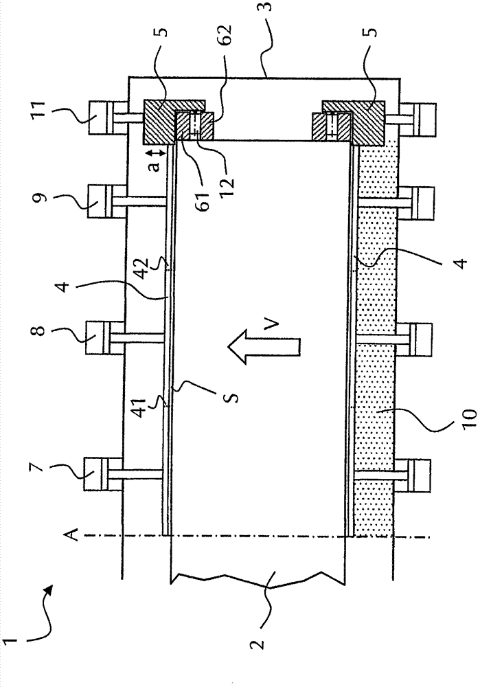
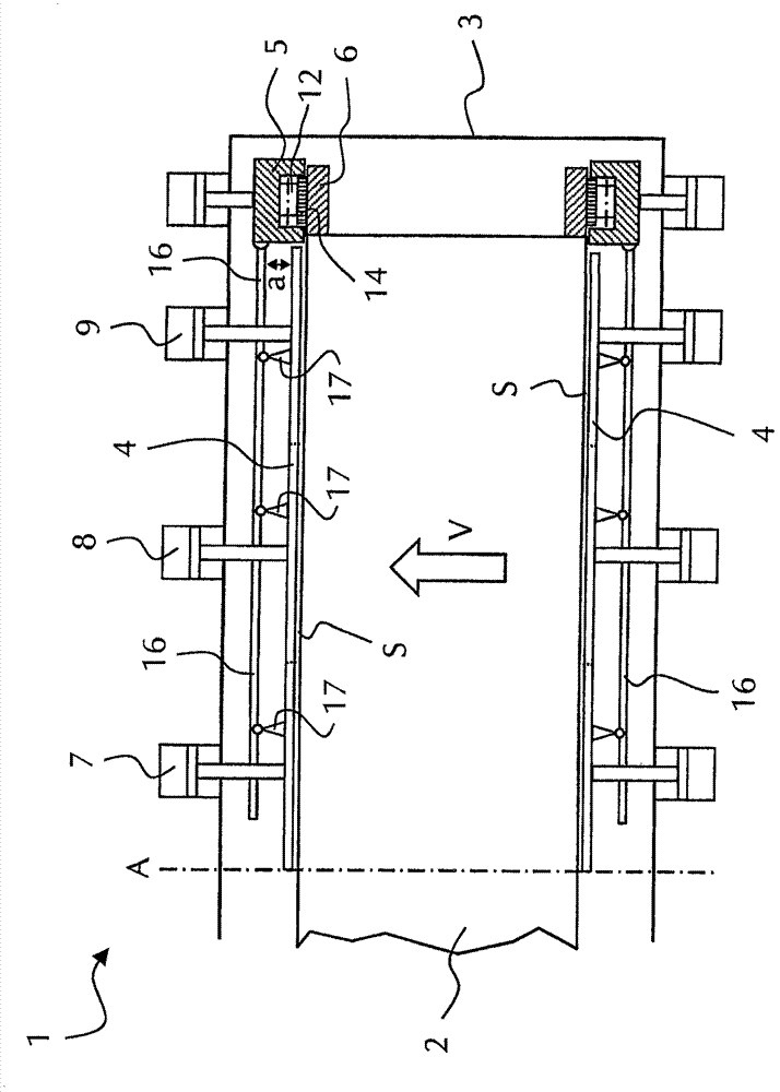
[0018] figure 1 A regenerative heat exchanger designated with reference number 1 is shown, of which only one half of the symmetrical structure is shown. The regenerative heat exchanger 1 comprises a rotor 2 which is held rotatably about a vertical axis of rotation A and is arranged in a rotor housing 3 . A plurality of gas volume flows V flow through the rotor 2 so that heat is transferred from at least one gas volume flow to at least another gas volume flow. A sealing system with a radial seal 4 and a circumferential seal 5 is provided for sealing the gas volume flow V guided through the regenerative heat exchanger 1 . The radial seal 4 is arranged on the front side of the rotor 2 and is provided for preventing a short-circuit volume flow between the gas volume flows V. FIG. The circumferential seal 5 is arranged on the face edge of the rotor 2 and is provided to prevent a leakage volume flow from entering the rotor housing 3 . The radial seal 4 and the circumferential sea...


PUM


Abstract

The regenerative heat exchanger (1) has a heat accumulator designed as rotor, where the accumulator is pivoted around a central rotary axis (A). The heat from a gas volume flow (V) arising by the rotor (2) is transferred to another gas volume flow arising by the rotor, where a sealing system is provided for the rotor. The sealing system has seals (4,5) fixed against the rotor. The seal on one hand is pressed on the rotor and on the other hand is held at the rotor.

Description

technical field [0001] The invention relates to a regenerative heat exchanger of the type according to the preamble of claim 1 . Background technique [0002] Various types of regenerative heat exchangers are used for heat transfer from at least one gas volume flow to at least another gas volume flow. The rotating heat accumulator, the so-called rotor, is heated by at least one gas volume flow and cooled again by at least another gas volume flow in an alternating manner, so that thermal energy is transferred from one gas volume flow to the other. As a result, one gas volume flow can be heated and the other gas volume flow can be cooled. The rotor consists of two face sides, an outer shroud and a partition that typically accommodates multiple heat accumulators. The rotor is held rotatably about a central rotational axis, which is preferably vertically aligned. [0003] In order to seal off the gas volume flow guided through the regenerative heat exchanger, a sealing system...

Claims


Application Information

Patent Timeline
IPC IPC(8): F28D19/04F16J15/16
CPCF28D19/047
Inventor 埃里希·博恩
Owner BALCKE DURR AG
Learn More