Eureka AIR delivers breakthrough ideas for toughest innovation challenges, trusted by R&D personnel around the world.

Method for producing a rotor/stator seal of a gas turbine

A gas turbine and stator sealing technology, which is used in engine manufacturing, machinery/engine, mechanical equipment, etc., can solve the problems of wear and tear of sealing material, blade tip entry, etc., to save fuel, prevent clogging, and have a small sealing effect.

Inactive Publication Date: 2013-03-20
LUFTHANSA TECH AG
View PDF4 Cites 1 Cited by
  • Summary
  • Abstract
  • Description
  • Claims
  • Application Information

AI Technical Summary

Problems solved by technology

In various operating states, penetration of the blade tip into the stator seal and abrasion of the material of the seal can occur without damage to the blade

Method used


Image

  • Method for producing a rotor/stator seal of a gas turbine
  • Method for producing a rotor/stator seal of a gas turbine
  • Method for producing a rotor/stator seal of a gas turbine

Examples


Embodiment Construction

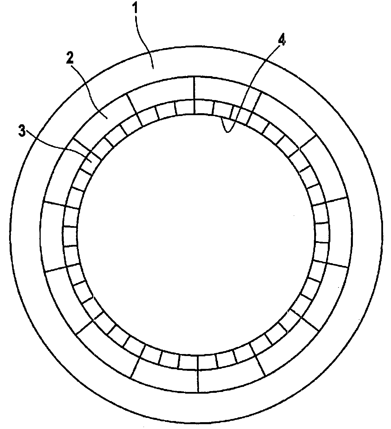
[0047] figure 2 A turbine housing 1 is shown in plan view, on the inner circumference of which a receiving section 2 for a sealing section 3 is arranged. The sealing segments 3 which adjoin one another on the circumference of the turbine housing 1 have sealing surfaces 4 on their radially inward circumferential surfaces.

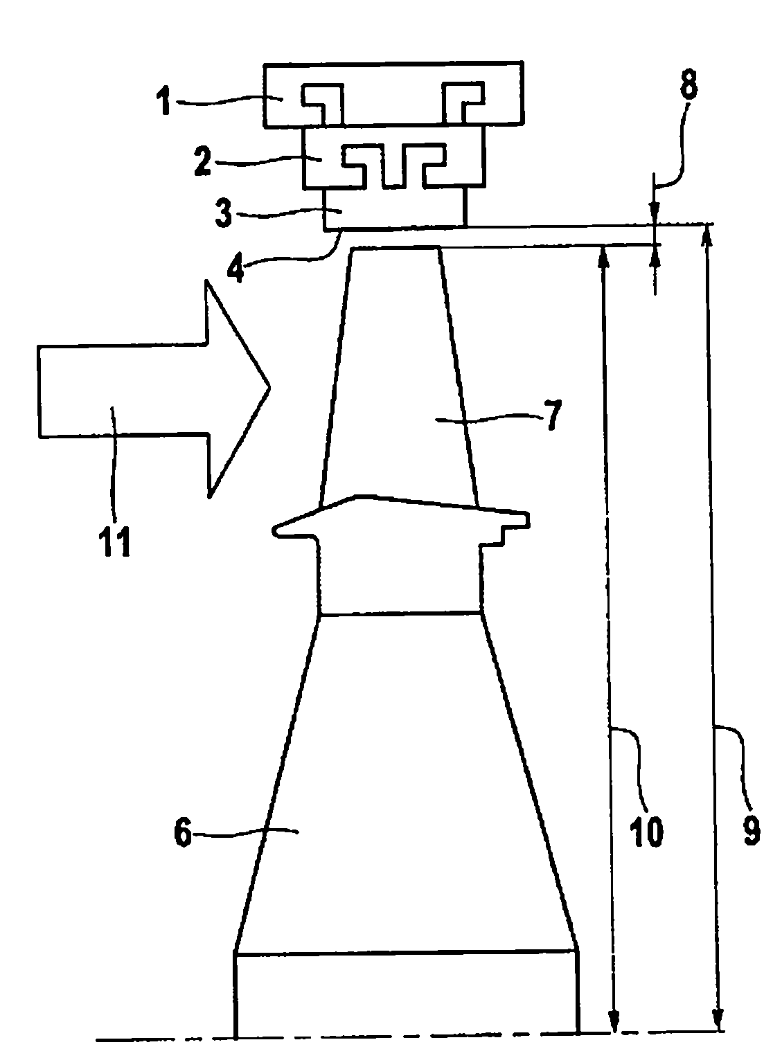
[0048] exist figure 1 The axis of rotational symmetry of the gas turbine is schematically indicated with reference numeral 5 in . A plurality of turbine blades 7 (rotor blades or rotor blades) are arranged distributed over the circumference on the rotor disk 6 . The radially outward tips of the turbine blades 7 seal against the sealing surface 4 of the sealing section 3 and enclose therewith a sealing gap 8 which can be calculated from the difference between the stator radius 9 and the rotor radius 10 . Arrow 11 indicates the direction of air flow through the gas turbine.

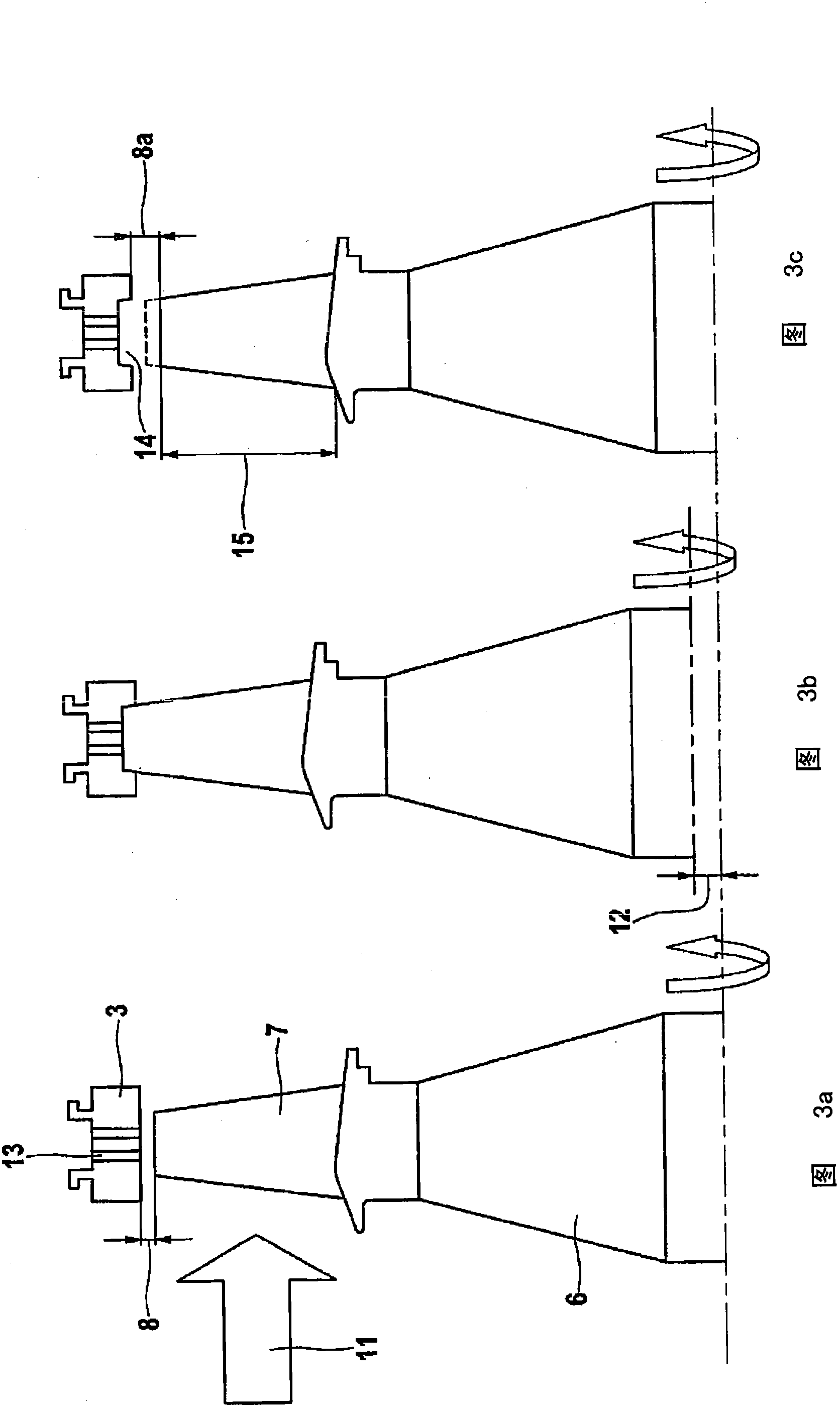
[0049] Figure 3a also shows figure 1 The initial state shown in . The sealin...


PUM

PropertyMeasurementUnit
thicknessaaaaaaaaaa
thicknessaaaaaaaaaa
thicknessaaaaaaaaaa

Abstract

The invention relates to a method for applying a ceramic layer (21) to the sealing surfaces (4) of sealing segments (3) arranged on the inner circumference of a turbine housing part (1) of a rotor / stator seal of a gas turbine. According to the invention, the ceramic layer (21) is applied while the sealing segments (3) are in an installed state in the turbine housing part (1).

Description

technical field [0001] The invention relates to a method for applying a ceramic layer to a sealing surface of a sealing segment of a gas turbine rotor / stator seal arranged on the inner circumference of a turbine housing part. Background technique [0002] In turbomachines, especially gas turbines, such as jet engines of aircraft, leakage flows caused by gaps between interacting and relatively moving rotor and stator parts reduce efficiency. In order to minimize clearance losses and thus maintain a high efficiency of a fluid machine or turbomachine, it is necessary to keep the clearance between the rotor blades, which usually rotate at high speed during machine operation, and the sealing surface of the housing surrounding the rotor belonging to the stator to be kept relatively small. Small. This is problematic because the rotor blades can elongate in the radial direction at high attachment not only due to thermal loads but also due to centrifugal forces, while the housing us...

Claims


Application Information

Patent Timeline
Patent Type & Authority Applications(China)
IPC IPC(8): C23C4/12C23C4/18C23C28/00B23P6/00F01D5/00F01D11/12
CPCC23C4/18F01D5/005B23P6/007F05D2230/10C23C28/00F05B2230/80F05D2230/312F01D11/122F05D2230/80C23C4/12Y02T50/67F05C2203/08F05D2300/21F05B2230/312F05B2230/10Y02T50/60
Inventor J·O·彼得斯V·蒂德曼C·W·西里D·施图恩茨
Owner LUFTHANSA TECH AG
Why Eureka
Eureka Blog
Learn More