Automatic code printing device of flat rectifier bridge

An automatic coding and rectifying bridge technology, which is applied to vibrating conveyors, transportation and packaging, conveyor objects, etc., can solve problems such as low efficiency and high labor intensity, and achieve the effect of improving coding efficiency and reducing labor intensity

Active Publication Date: 2014-07-09
HUANGSHAN QIMEN XINFEI ELECTRONICS TECH DEV
View PDF8 Cites 0 Cited by
  • Summary
  • Abstract
  • Description
  • Claims
  • Application Information

AI Technical Summary

Problems solved by technology

[0003] After the flat rectifier bridge is manufactured, it is necessary to mark the product model on the surface of the flat shell 1. When the existing flat rectifier bridge is coded, the flat rectifier bridge after manufacture is generally manually placed on the existing coding machine. And it is necessary to manually align the surface of the flat shell 1 with the printing dock, only one can be printed at a time, and it needs to be manually put on it one by one to print in sequence
[0004] For the coding of batches of flat rectifier bridges, this coding method is extremely inefficient and labor-intensive

Method used


Image

  • Automatic code printing device of flat rectifier bridge
  • Automatic code printing device of flat rectifier bridge
  • Automatic code printing device of flat rectifier bridge

Examples


Embodiment Construction

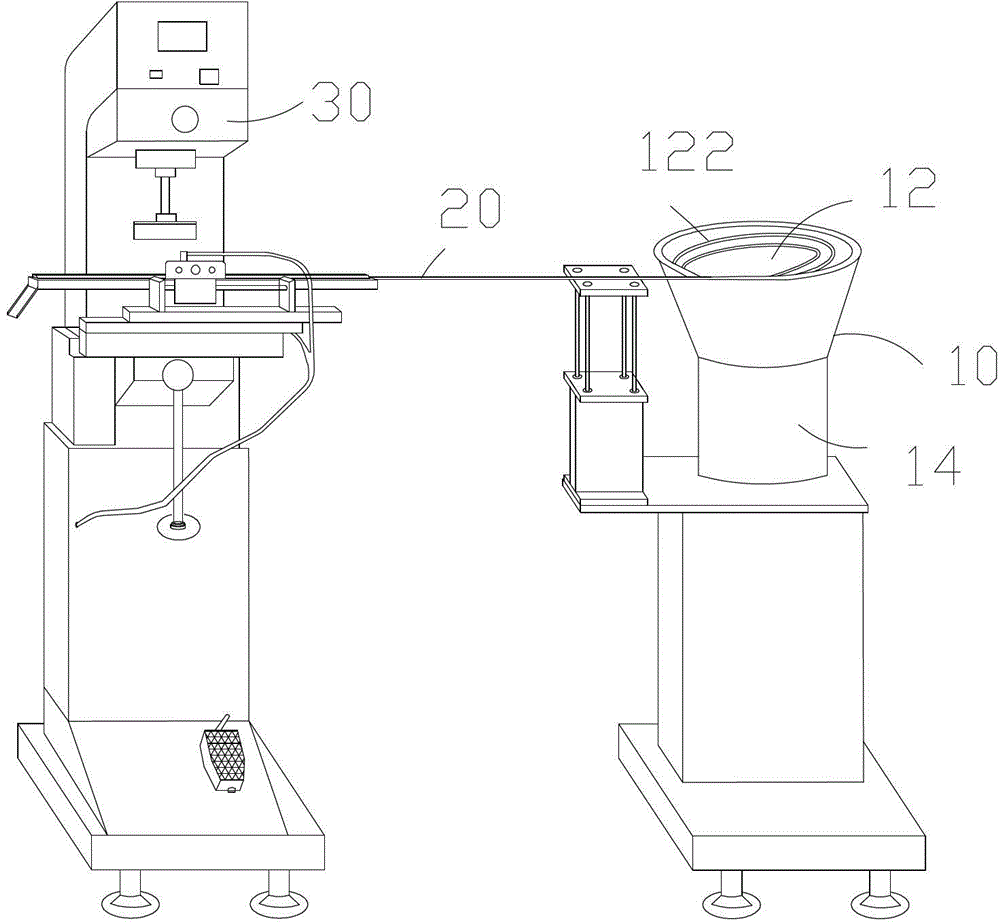
[0021] see figure 2 As shown, the automatic coding device of the flat rectifier bridge of the present invention includes a feeding device 10 , a coding device 20 , and a coding machine 30 .

[0022] The coding machine 30 can use existing coding machines on the market.

[0023] The feeding device 10 includes a feeding chute 12 and a vibrating device 14 located at the lower part of the feeding chute 12 . The inner periphery of the feeding trough 12 is provided with a channel 122 that goes up spirally. First, all the flat rectifier bridges that need to be coded are poured into the feeding trough 12, and the vibration of the vibration device 14 drives the flat rectifier bridges to spiral up along the channel 122 in sequence until reaching the code device 20.

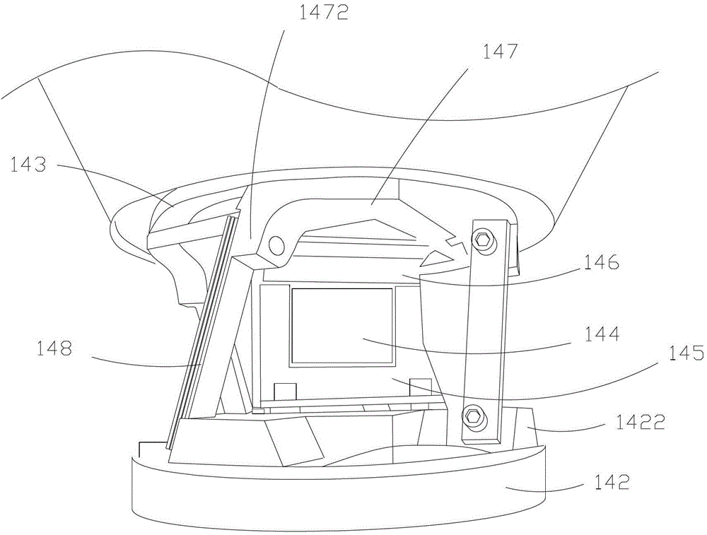
[0024] see image 3 As shown, the vibrating device 14 includes a housing ( image 3 Middle shell has been removed), bottom plate 142, top plate 143, coil 144, first magnetic steel 145, second magnetic steel 146, fixed p...


PUM


Abstract

An automatic code printing device of a flat rectifier bridge comprises a code printing machine, a feeding device and a code material device, wherein the feeding device comprises a feeding groove and a vibration device located on lower part of the feeding groove; a spiraling channel is arranged on the inner circumference of the feeding groove; the vibration of the vibration device drives the flat rectifier bridge in the feeding groove to arrive at the code material channel along the spiraling channel; the code material device comprises a feeding device, a finishing device and a discharging device; and the flat rectifier bridge enters the finishing device located under the head of the code printing machine by the feeding device and then is output from the discharging device. The automatic code printing device has the advantages of achieving batch automatic code printing, drastically improving code printing efficiency and notably reducing labor intensity.

Description

technical field [0001] The invention relates to a coding device, in particular to an automatic coding device for a rectifier bridge. Background technique [0002] The structure of the existing flat rectifier bridge is as follows figure 1 As shown, it includes a flat shell 1, an epoxy resin potting body 2, a rectifier diode (not shown) and an electrode pin 3, the electrode pin 3 is welded on the rectifier diode, and the rectifier diode is sealed by an epoxy resin potting body 2 is packaged in a flat case 1. [0003] After the flat rectifier bridge is manufactured, it is necessary to mark the product model on the surface of the flat shell 1. When the existing flat rectifier bridge is coded, the flat rectifier bridge after manufacture is generally manually placed on the existing coding machine. And it is necessary to manually align the surface of the flat shell 1 with the docking station, which can only be printed one at a time, and it needs to be manually put on one by one t...

Claims


Application Information

Patent Timeline
Patent Type & Authority Patents(China)
IPC IPC(8): B65G27/02B65G27/24B65G47/26B65G47/74
Inventor 胡文新周小妹汪华锋吴翠丰
Owner HUANGSHAN QIMEN XINFEI ELECTRONICS TECH DEV
Why Eureka
Try Eureka