
Radar imaging device, imaging method and program therefor

A radar imaging and corresponding technology, which is used in measurement devices, directional guides for determining directions, reflection/re-radiation of radio waves, etc., can solve the problems of inability to detect the direction of moving targets, long time, and sensitivity decline.

Inactive Publication Date: 2012-10-31
PANASONIC CORP
View PDF5 Cites 10 Cited by
  • Summary
  • Abstract
  • Description
  • Claims
  • Application Information

AI Technical Summary

Problems solved by technology

However, there is a problem with systems using infrared rays that it is difficult to distinguish between a person's body temperature and the external environment in places where the temperature is high.
In addition, there is a problem in systems using cameras that the sensitivity drops sharply at night or in environments where sufficient light cannot be obtained, such as in bad weather.
Due to the increase in processing time as described above, there may be cases where the direction of the moving target cannot be detected
[0034] Also, even if the configuration of Patent Document 1 is applied to the configuration for detecting the Doppler frequency, it takes a long time to analyze the Doppler frequency, so the processing time also increases.
That is, there is a problem that the direction of a moving target cannot be detected

Method used


Image

  • Radar imaging device, imaging method and program therefor
  • Radar imaging device, imaging method and program therefor
  • Radar imaging device, imaging method and program therefor

Examples


Embodiment 1)

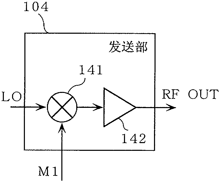
[0084] figure 1 It is a block diagram showing the configuration of the radar device 100 according to the first embodiment. in addition, figure 1 200 a and 200 b which are targets (objects) to be detected by the radar device 100 are also shown in .

[0085] The radar device 100 is a radar imaging device of the present invention, and has a function of detecting line-of-sight speed and direction of the targets 200a and 200b, and a function of measuring distances to the targets 200a and 200b using spreading codes.

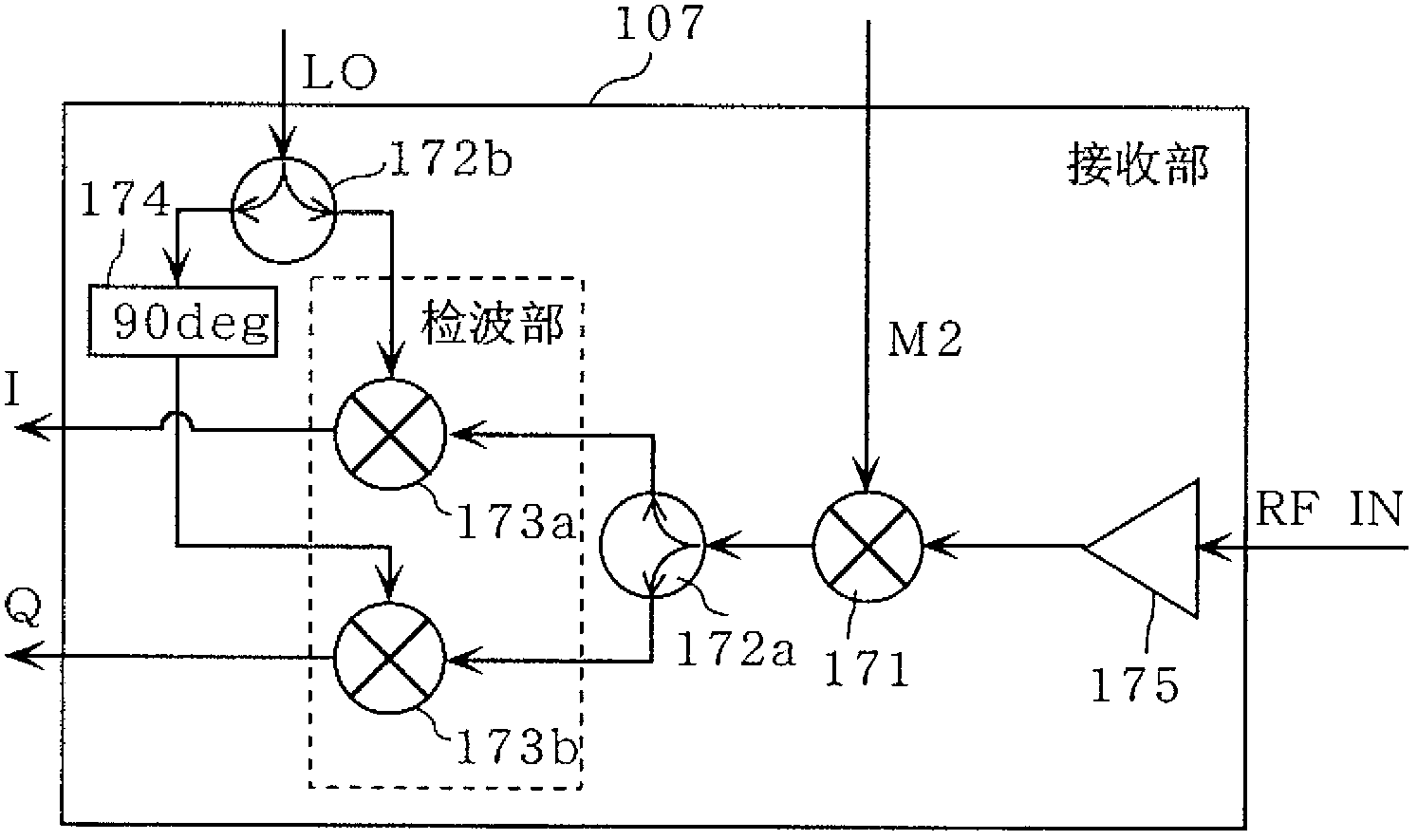
[0086] Specifically, the radar device 100 includes: an oscillator 101, distributors 102a and 102b, a spreading code generating unit 103a, a delay code generating unit 103b, a transmitting unit 104, a transmitting antenna 105, receiving antennas 106a and 106b, a receiving unit 107a and 107b, a signal processing unit 108, analog-digital converters 109a, 109b, 109c, and 109d, and a control unit 110. Furthermore, the objects 200a and 200b are referred to as the object...

Embodiment 2)

[0213] Next, a radar device according to Embodiment 2 will be described.

[0214] The radar device according to the present invention is almost the same as the radar device 100 according to Embodiment 1, and further includes a control unit that controls a first operation mode and a second operation mode. The first operation mode refers to: The delay code generation unit 103b repeatedly performs scanning processing for M times. The second operation mode refers to repeatedly generating the same delay code M2; The units 182a and 182b detect whether or not there is a Doppler frequency component whose intensity is equal to or greater than a predetermined second threshold, and if it is judged that there is a Doppler frequency component equal to or greater than the predetermined second threshold, switch to the The second mode of operation; in the second mode of operation, the delay code generating unit 103b repeatedly generates the delay code M2 ​​corresponding to the range gate whos...


PUM


Abstract

A radar imaging device is provided with a delay code generating unit (103b), signal storage units (181a and 181b), a memory control unit (185), Doppler frequency determination units (182a and 182b), and an incoming direction calculation unit (183). During a scanning period in which N range gates that are at different distances from the radar imaging device are scanned, the delay code generating unit (103b) repeats, for M scanning periods, scanning processing in which N delay codes (M2) corresponding to the range gates are generated by a transmission code (M1). The signal storage units (181a and 181b) store baseband signals (Rij) corresponding to the range gates and the scanning period. For M scanning periods, the memory control unit (185) repeatedly writes N detection signals (R1j to RNj) corresponding to a single scanning period to the signal storage units (181a and 181b). The memory control unit (185) also reads sets of M detection signals (Ri1 to RiM) corresponding to mutually different scanning periods. The Doppler frequency determination units (182a and 182b) perform frequency analysis of the detection signals (Ri1 to RiM) of the same range gate. The incoming direction calculation unit (183) estimates the direction of a target.

Description

technical field [0001] The present invention relates to a radar imaging device, an imaging method, and the like for detecting a target object by emitting a transmission signal and receiving a reflected wave of the transmission signal reflected from the object. Background technique [0002] In recent years, there has been an increasing demand for human body testing for the purpose of security and safety, regardless of the field in society. In addition to countermeasures against terrorism, which has become widespread in the world, human detection has become an important issue in elderly care and disaster relief. Conventional methods have used infrared devices and cameras to detect people. However, there is a problem in a system using infrared rays that it is difficult to distinguish between a person's body temperature and the external environment in places where the temperature is high. In addition, there is a problem in a system using a camera that the sensitivity drops sha...

Claims


Application Information

Patent Timeline
Patent Type & Authority Applications(China)
IPC IPC(8): G01S13/89G01S13/28G01S13/42G01S13/50
CPCG01S13/288G01S13/64G01S3/48G01S2007/2886G01S13/89G01S7/2886
Inventor 福田健志井上谦一佐藤亨阪本卓也佐保贤志
Owner PANASONIC CORP
Learn More