Polygonal image digitizing method utilizing rotating TIN (triangulated irregular network)

A polygon and image technology, applied in image data processing, image coding, instruments, etc., can solve the problems of unfavorable coordination between pixel shapes and no comprehensive analysis of digital processing results, etc., to achieve convenient network construction, program control, and algorithm simple effect

Inactive Publication Date: 2015-07-08
黄桂芝
View PDF1 Cites 0 Cited by
  • Summary
  • Abstract
  • Description
  • Claims
  • Application Information

AI Technical Summary

Problems solved by technology

[0003] The purpose of the present invention is to provide a kind of image digitalization method that adopts the comprehensive analysis of rotating TIN network, to solve the unfavorable coordination between the shapes of the pixels in the image digitalization method in the field of image digital processing, and the comprehensive analysis of the digital processing results is not carried out. defect

Method used


Image

  • Polygonal image digitizing method utilizing rotating TIN (triangulated irregular network)
  • Polygonal image digitizing method utilizing rotating TIN (triangulated irregular network)
  • Polygonal image digitizing method utilizing rotating TIN (triangulated irregular network)

Examples


specific Embodiment approach 1

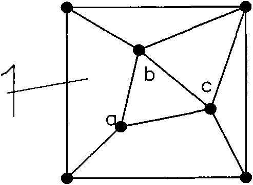
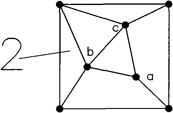
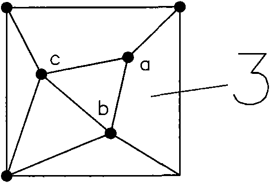
[0009] Specific implementation mode one: the following combination Figure 1 to Figure 6 This embodiment will be specifically described. This embodiment includes the following steps: 1. Taking 30mm as the side length of the basic square; 2. Arranging one control point at each of the four vertices of the basic square, and distributing three control points in the basic square, see schematic diagram figure 1 , the plane coordinates of the four vertices are (0, 0), (30, 0), (30, 30) and (0, 30), point a is (9, 9), point b is (12, 22.5) , point c is (24, 12), the above three points a, b, and c are connected to form a triangle, and then select a vertex from the four vertices of the basic square, and the distance between the vertex and the two vertices of the inner triangle adjacent to it The sum is the smallest, connect the selected control point at the vertex of the square with the control points at the two vertices of the adjacent inner triangle mentioned above, and pass through ...

specific Embodiment approach 2

[0010] Embodiment 2: The difference between this embodiment and Embodiment 1 is that step A is also included between step 4 and step 5, and the length or width direction of the supporting unit is scaled to make it a rectangle, and the positions of all control points inside Adjust to scale. Other steps are still the same as those in Embodiment 1.


PUM


Abstract

Disclosed is a polygonal image digitizing method utilizing a rotating TIN (triangulated irregular network). The polygonal image digitizing method aims to overcome the shortcoming that echoes and matching of existing pixels are insufficient. The polygonal image digitizing method comprises the following steps of determining the side length of a basic square according to a Shannon's sampling theorem; arranging one sampling point at each of four vertexes of the basic square, and arranging 3 sampling points in the basic square in a scattered manner to form a basic unit; counterclockwise rotating the basic unit to form a primary unit body, a secondary unit body and a tertiary unit body; splicing the basic unit, the primary unit body, the secondary unit body and the tertiary unit body to form a square assorted unit; utilizing the assorted unit as a replication unit, and performing translation replication repeatedly to form a sampling network covering an image; and utilizing control points in the sampling network as centers to relatively uniformly divide the area in the range of the sampling network into polygons by straight lines, utilizing the areas of the small polygons as sampling units, utilizing brightness values of feature points as brightness values of the sampling units when the feature points are arranged in the sampling units, and utilizing brightness values of the control points in the sampling units as brightness values of the sampling units so as to finish digitization of an image when the feature points are not arranged in the sampling units.

Description

technical field [0001] The invention relates to an image digitization method in the field of image digital processing. Background technique [0002] The image digitization method in the field of image digital processing consists of two parts: sampling and quantization. The shape of the pixel in the sampling process can be various shapes such as regular triangle, square, regular hexagon, etc., and the shape of square, especially square is often used. Its shortcoming is that it does not take better consideration of the echo of adjacent pixels to control the object better; it does not take better consideration of the division of control distance in all directions. Contents of the invention [0003] The purpose of the present invention is to provide a kind of image digitalization method that adopts the comprehensive analysis of rotating TIN network, to solve the unfavorable coordination between the shapes of the pixels in the image digitalization method in the field of image ...

Claims


Application Information

Patent Timeline
Patent Type & Authority Patents(China)
IPC IPC(8): G06T9/00
Inventor 黄桂芝
Owner 黄桂芝
Why Eureka
Try Eureka