Assembling structure of suspended ceiling

A technology for assembling structures and ceilings, applied in the field of architectural decoration, can solve the problems of cluttered ceilings, inconvenient installation, disassembly or replacement, etc., and achieve the effects of simple component structure, low cost, and clean structure

Inactive Publication Date: 2012-10-31
徐建光
View PDF6 Cites 1 Cited by
  • Summary
  • Abstract
  • Description
  • Claims
  • Application Information

AI Technical Summary

Problems solved by technology

[0002] As we all know, various functional equipment terminals are usually installed on the indoor ceiling of a building, such as lighting, fire protection, HVAC, monitoring, alarm, etc., and such functional equipment terminals cause the ceiling to form a messy structure, and such functional equipment terminals are not easy to install , remove or replace

Method used


Image

  • Assembling structure of suspended ceiling
  • Assembling structure of suspended ceiling
  • Assembling structure of suspended ceiling

Examples


Embodiment 1

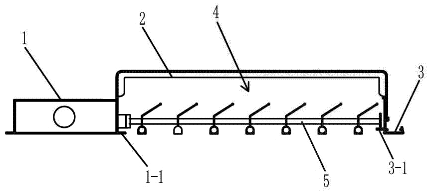
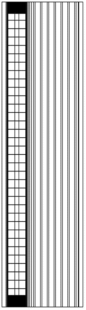
[0046] Embodiment one: see figure 1 , 2 The assembly structure of the suspended ceiling in this embodiment includes a light frame 1, a connecting frame 2, and a side plate 3. The light frame 1 is equipped with a luminous body, and the lower opening of the light frame can be equipped with a light-transmitting plate or a light-transmitting cover. Pass through the light-transmitting plate or light-transmitting cover of the light frame to illuminate the outside. The light frame 1 and the side plate 3 are arranged in parallel with a distance, and the two are fixedly connected by the connecting frame 2 . Thus, a functional space 4 is formed between the lamp holder 1 and the side plate 3, and various functional equipment terminals can be placed in this functional space. There is a grid plate 5, which has a decorative effect and a tuyere diversion effect. In this embodiment, the lamp holder 1 and the side plate 3 respectively form a shelf 1-1 and 3-1 facing opposite sides, and a gr...

Embodiment 2

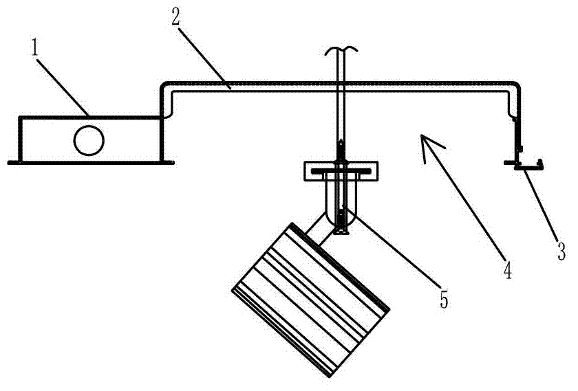
[0047] Embodiment two: see image 3 , 4 , in this embodiment, the functional equipment terminal is the guide rail spotlight 5, and the guide rail spotlight 5 is fixed on the top surface of the building ceiling.

[0048] There is no grid plate in this embodiment, and the other contents are the same as in the first embodiment, refer to the first embodiment.

Embodiment 3

[0049] Embodiment three: see Figure 5 , the assembly structure of the suspended ceiling in this embodiment includes a light frame 1, a connecting frame 2, and a light frame 3. Light-emitting bodies are installed in the two light frames. The lower opening of the light frame can be equipped with a light-transmitting plate or a light-transmitting cover. The light shines to the outside through the light-transmitting panels or light-transmitting covers of the respective lamp stands. The two light frames are arranged in parallel with a distance between them, and the two are fixedly connected by the connecting frame 2 . Thus, a functional space 4 is formed between the two lamp holders, and various functional equipment terminals can be placed in this functional space. In this embodiment, the functional device terminal is a point light source 5 installed on the connecting frame 2 .


PUM


Abstract

The invention discloses an assembling structure of a suspended ceiling. The assembling structure comprises a first lamp holder which is internally provided with a first luminous body, a lateral plate or a second lamp holder which is internally provided with a second luminous body, and a connecting frame, wherein the first lamp holder and the lateral plate or the second lamp holder are connected through the connecting frame; and a functional space is formed between the first lamp holder and the lateral plate or the second lamp holder. The assembling structure of the suspended ceiling, disclosed by the invention, is provided with one functional space, a plurality of functional equipment terminals can be placed in the functional space and the functional space also can be communicated with an air opening of the suspended ceiling, so that the structure of the whole suspended ceiling is clean and ordered; and the functional equipment terminals can be mounted, detached or replaced conveniently.

Description

technical field [0001] The invention belongs to the technical field of architectural decoration, in particular to an assembly structure of a suspended ceiling. Background technique [0002] As we all know, various functional equipment terminals are usually installed on the indoor ceiling of a building, such as lighting, fire protection, HVAC, monitoring, alarm, etc., and such functional equipment terminals cause the ceiling to form a messy structure, and such functional equipment terminals are not easy to install , Disassemble or replace. Contents of the invention [0003] In order to solve the above-mentioned problems in the prior art, the present invention provides an assembly structure of a suspended ceiling. [0004] The present invention adopts the following technical solutions: an assembly structure of a suspended ceiling, including a first light frame with a built-in illuminant, a side plate or a second light frame with a built-in luminous body, and a connecting fr...

Claims


Application Information

Patent Timeline
Patent Type & Authority Applications(China)
IPC IPC(8): E04F13/074
Inventor 徐建光
Owner 徐建光
Why Eureka
Try Eureka