
Left turning system for non-power-driven vehicle at intersection

A technology for intersections and non-motor vehicles, applied in the field of left-turn systems for non-motor vehicles at intersections, can solve the problems of invariable phases, delays of non-motor vehicles or motor vehicles, discontinuity of right-turn motor vehicles, etc., so as to avoid safety accidents. , optimize the effect of road traffic

Active Publication Date: 2012-10-31
SHANGHAI URBAN CONSTR DESIGN RES INST GRP CO LTD
View PDF6 Cites 9 Cited by
  • Summary
  • Abstract
  • Description
  • Claims
  • Application Information

AI Technical Summary

Problems solved by technology

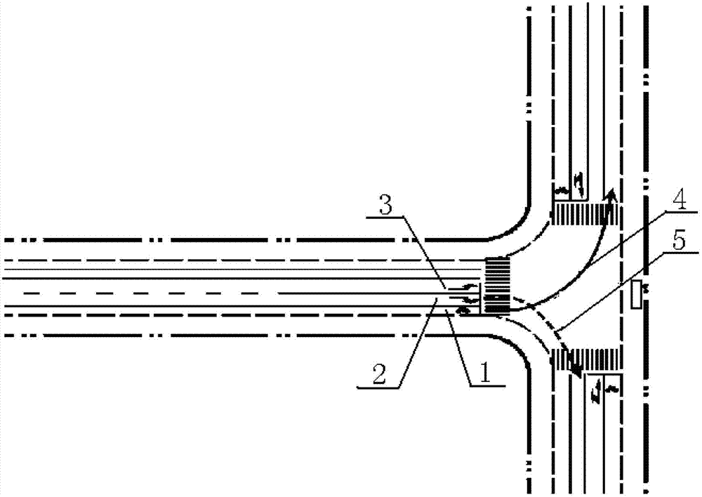
[0003] 1. Left-turning non-motor vehicle traffic flow 4 often interferes with right-turning motor vehicle traffic flow 5 and conflicts, resulting in delays and queues for non-motor vehicles or motor vehicles, thereby reducing the traffic capacity of the entire intersection and discontinuous right-turning motor vehicles
[0004] 2. If the left-turning phase and the right-turning phase are separated, when the non-motor vehicle stops in front of the red light for the left-turning vehicle, it will affect the passage of the right-turning non-motorized vehicle
[0005] 3. Non-motor vehicles turning left and motor vehicles turning right are prone to danger, and non-motor vehicles are less safe
[0006] 4. It is impossible to estimate the flow of non-motorized vehicles turning left and right at different times, considering the flow direction of non-motorized vehicles at different times in the morning and evening peak hours, and the phase is not variable

Method used


Image

  • Left turning system for non-power-driven vehicle at intersection
  • Left turning system for non-power-driven vehicle at intersection
  • Left turning system for non-power-driven vehicle at intersection

Examples


Embodiment Construction

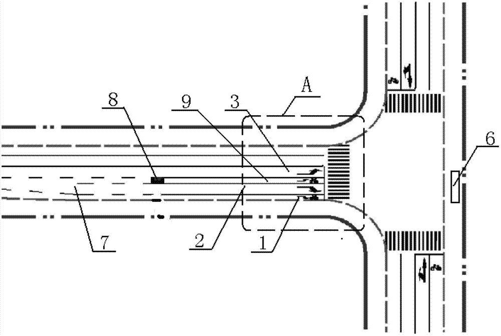
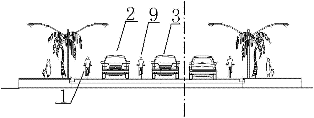
[0027] like figure 2 - Figure 5 Shown is a specific embodiment of the non-motor vehicle turning left system at the intersection of the present invention. The non-motor vehicle turning left system at the intersection includes sensing facilities 8 for detecting the number of non-motor vehicles, a left-turn signal light, The non-motor vehicle left-turn lane 9 adjacently arranged on the right side of the motor vehicle left-turn lane 3 is used for the interweaving section 7 of right-turn motor vehicles and left-turn non-motor vehicle lane change.

[0028] The interweaving section 7 is arranged on the right-turning lane 2 of motor vehicles and the left-turning lane 9 of non-motor vehicles, so that right-turning motor vehicles and left-turning non-motorized vehicles can be changed to the corresponding lanes before reaching the intersection, so that the left-turning at the intersection Non-motor vehicle traffic flow 5 and right-turning motor vehicle traffic flow 4 pass without conf...


PUM


Abstract

The invention discloses a left turning system for a non-power-driven vehicle at an intersection. The left turning system comprises an induction facility, a left turning signal light, a non-power-driven vehicle left turning lane and a crossover section, wherein the induction facility is used for detecting the quantity of non-power-driven vehicles; the non-power-driven vehicle left turning lane is arranged adjacent to the right side of a power-driven vehicle left turning lane; the crossover section is used for changing the lanes for a right turning power-driven vehicle and a left turning non-power-driven vehicle and is arranged on the power-driven vehicle right turning lane and the non-power-driven vehicle left turning lane; and the induction facility is arranged on the non-power-driven vehicle left turning lane and is connected with the left turning signal light. With the adoption of the left turning system for the non-power-driven vehicle at the intersection, the non-power-driven vehicle can directly turn leftwards quickly and safely, the passage of the right turning non-power-driven vehicle is not influenced, and the clash between the left turning non-power-driven vehicle and straight power-driven vehicle or between the left turning non-power-driven vehicle and the right turning power-driven vehicle can be avoided.

Description

technical field [0001] The invention relates to the technical field of traffic roads, in particular to a left-turning system for non-motor vehicles at intersections. Background technique [0002] At present, at the intersection of traffic roads, especially the T-junction where ordinary low-grade roads (mainly branch roads) intersect, such as figure 1 The schematic diagram of a conventional intersection shown has the following problems: [0003] 1. The left-turning non-motor vehicle traffic flow 4 often interferes with the right-turning motor vehicle traffic flow 5 and conflicts, causing non-motor vehicles or motor vehicles to delay and queue up, thereby reducing the traffic capacity of the entire intersection and discontinuous right-turning motor vehicles. [0004] 2. If the left-turning phase and the right-turning phase are separated, when the non-motor vehicle stops ahead and becomes a red light for a left-turning vehicle, it will affect the passage of a right-turning n...

Claims


Application Information

Patent Timeline
IPC IPC(8): E01C1/02
Inventor 彭庆艳王啸君庄捷黄昊蒋应红
Owner SHANGHAI URBAN CONSTR DESIGN RES INST GRP CO LTD
Learn More