
Spring assembly machine for spring lock

A technology for assembly machines and pin locks, applied in metal processing, metal processing equipment, manufacturing tools, etc., can solve problems such as difficult export of spring holes, low work efficiency, and spring drop

Inactive Publication Date: 2012-10-31
瑞安市东华自动化科技有限公司
View PDF10 Cites 11 Cited by
  • Summary
  • Abstract
  • Description
  • Claims
  • Application Information

AI Technical Summary

Problems solved by technology

It can be seen that this kind of spring installation device has only one material guide tube. Generally, the pin lock spring on the pin lock can only be filled with the spring through multiple slides of the slide table. The work efficiency is not high, and the slide table is moving. Among them, the spring hole on the spring template is difficult to connect with the outlet of the feeding head, which often causes the spring to fall, and the spring cannot be loaded into a certain hole of the pin lock.

Method used


Image

  • Spring assembly machine for spring lock
  • Spring assembly machine for spring lock
  • Spring assembly machine for spring lock

Examples


Embodiment 1

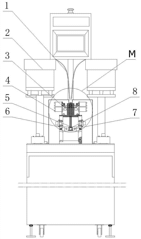
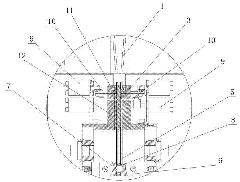
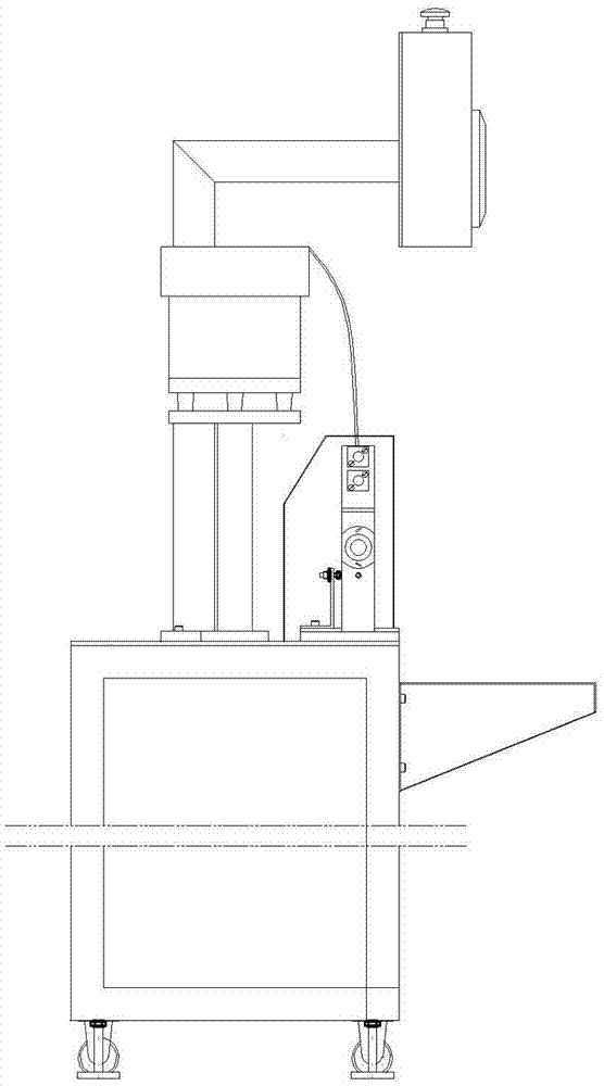
[0016] Embodiment one: refer to Figure 1~Figure 3 , this pin lock spring assembly machine includes a spring feeder 2, a feed pipe 1, a mold base 6, a feed head 3 and a material control device, and the feed head 3 has a number of longitudinal passages 12 arranged in a line for springs to pass through, The quantity of the longitudinal channel 12 corresponds to the quantity of pinholes on the tumbler lock cylinder. The material control device is installed on the side of the feeding head 3. The material control device includes a first material control device and a second material control device. The first material control device is arranged above the second material control device, and both the first material control device and the second material control device include a transverse through hole 11, a support rod 10 and a first cylinder 9, and the transverse through hole 11 communicates with the longitudinal channel 12 , and the support rod 10 is installed on the push rod of the ...

Embodiment 2

[0017] Embodiment two: refer to Figure 4~Figure 6 , in this embodiment, wherein the structure of the mold base is different from that of Embodiment 1, the difference is that the station for placing the lock core is a lock core mold pad 16, and a slidable slide plate 14 is installed on the mold base 6 , the second air cylinder 15 is installed on the slide plate 14 , and the die pad 16 is connected with the second air cylinder 15 . Other structures are the same as in Embodiment 1. The structure of the lock cylinder in this embodiment is different from that in Embodiment 1. In the lock cylinder of Embodiment 1, the pin hole is arranged on the side of the lock core, and the pin hole and the key hole on the lock core are perpendicular to each other. For the lock core in this embodiment, the pin hole is arranged on the end surface of the lock core, and the pin hole and the key hole are parallel to each other, therefore, the lock core needs to be placed upright. Therefore, when as...


PUM


Abstract

The invention discloses a spring assembly machine for a spring lock. The spring assembly machine for the spring lock is characterized by comprising a spring feeder, a feeding pipeline, a die holder, a feeding head and a material control device; the feeding head is provided with a plurality of vertical channels which are arranged in straight-line shapes and allow springs to pass through; the material control device is mounted on the side face of the feeding head; one end of the feeding pipeline is connected with the spring feeder, and the other end of the feeding pipeline is correspondingly communicated with the vertical channels; the die holder is provided with a spring channel corresponding to the feeding head and a station for placing a lock core; and the spring channel is correspondingly communicated with the vertical channels on the feeding head. With the adoption of the structure provided by the invention, the springs can be automatically fed in a spring hole of the lock core of a lock. The spring assembly machine has the advantages of convenience in operation, rapidness in assembly and no occurrence of neglected loading; and very high production efficiency can be brought to the assembly of the springs of the lock core.

Description

technical field [0001] The invention relates to a machine for assembling springs on locks, in particular to a machine for assembling lock core springs on locks. Background technique [0002] At present, the application range of the pin lock is very wide. Among them, the lock cylinder of the pin lock is provided with holes for assembling pins and springs. The spring holes on the lock core basically have two ways of setting on the lock core, one The spring hole is perpendicular to the keyhole on the lock cylinder, the other is parallel to the keyhole on the lock cylinder, and the spring holes perpendicular to the keyhole of the lock cylinder are provided with multiple rows on the lock cylinder, and some are in the lock. The cores are arranged symmetrically, and some are perpendicular to each other; and the spring holes parallel to the keyhole are arranged around the keyhole. Regardless of the structure of the lock cylinder, springs must be assembled when the pins are installed...

Claims


Application Information

Patent Timeline
Patent Type & Authority Applications(China)
IPC IPC(8): B23P19/00
Inventor 周章东贺树良
Owner 瑞安市东华自动化科技有限公司
Learn More