Flywheel brake device for punch press

A braking device and flywheel technology, applied in safety equipment, metal processing equipment, manufacturing tools, etc., can solve hidden dangers, existing safety, safety problems and other problems, and achieve the effect of good safety and fast process

Inactive Publication Date: 2012-10-31
ZHEJIANG JINAOLAN MASCH TOOL CO LTD
View PDF6 Cites 3 Cited by
  • Summary
  • Abstract
  • Description
  • Claims
  • Application Information

AI Technical Summary

Problems solved by technology

[0002] At present, after the punch press is stopped, because the flywheel itself has great energy, it needs to rely on long-term rotation and its own friction to stop the flywheel. In this case, if the clutch moves, it will cause certain damage. security issues, security risks

Method used


Image

  • Flywheel brake device for punch press
  • Flywheel brake device for punch press

Examples


Embodiment Construction

[0010] The present invention will be further described in detail below in conjunction with the accompanying drawings and embodiments.

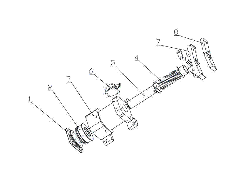
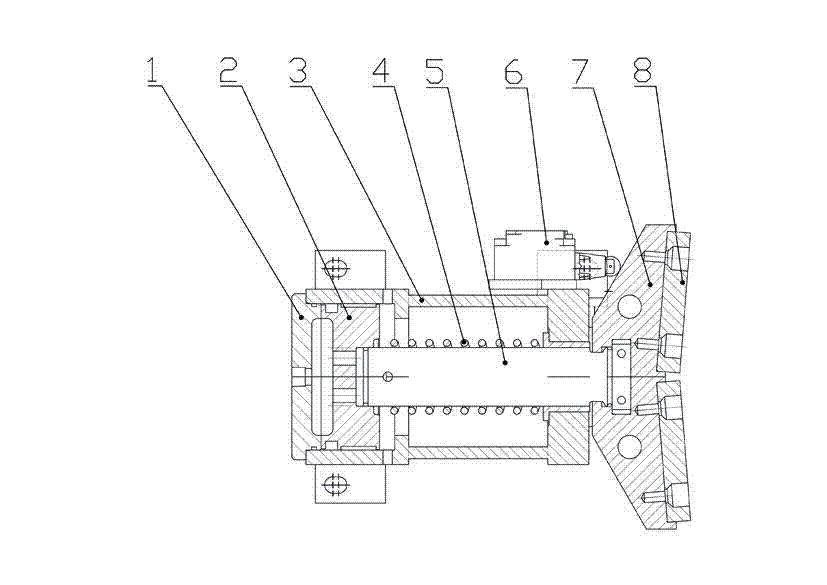
[0011] Such as figure 1 , 2 As shown, a flywheel braking device for a punch press includes a gland 1, a cylinder 3 and a friction block 8, the gland is arranged outside the cylinder, and the gland is provided with an air inlet for inflating and pressing the piston; The cylinder includes a piston rod 5, a piston 2 and a cylinder body, a spring 4 is arranged in the cylinder body, and the spring is sleeved on the piston rod, one end is against the piston, and the other end is against the inner wall of the cylinder; The friction block is installed on the friction block seat 7, and the friction block seat is arranged on the other side of the cylinder body, and the free end of the piston rod is fixedly connected with the friction block seat; Contact switch 6 at the position of the friction block seat.


PUM


Abstract

The invention discloses a flywheel brake device for a punch press. The flywheel brake device comprises a gland, an air cylinder and a friction block, wherein the gland is arranged on the outer side of the air cylinder; an air inlet for applying pressure to a piston in an inflation mode is formed on the gland; the air cylinder comprises a piston rod, the piston and a cylinder body; a spring is arranged in the cylinder body and is sleeved on the piston rod; one end of the piston rod butts against the piston, and the other end of the piston rod butts against the inner wall of the cylinder body; a friction block is arranged on a friction block base; the friction block base is arranged on the other side of the cylinder body; the free end of the piston rod is fixedly connected with the friction block base; and a contact switch for judging the position of the friction block base is arranged on the cylinder body of the air cylinder. The flywheel brake device achieves the function of stopping a flywheel quickly by virtue of a principle of converting mechanical energy into heat energy through adding resistance to quickly consume the energy of the flywheel, so that the whole process is fast and simple in, and the flywheel brake device is good in security and suitable for industrial popularization.

Description

technical field [0001] The invention relates to a flywheel braking device for a punch press. Background technique [0002] At present, after the punching machine is stopped, because the flywheel itself has great energy, it needs to rely on long-term rotation and its own friction to stop the flywheel. In this case, if the clutch moves, it will cause certain damage. There are security issues and hidden dangers. Contents of the invention [0003] The present invention mainly solves the shortcomings of the existing above-mentioned technologies, and provides a flywheel braking device for a punch press that can quickly stop the flywheel after the punch press stops. [0004] The technical solution adopted by the present invention to solve the problems of the technologies described above is: [0005] A flywheel braking device for a punch press, comprising a gland, a cylinder and a friction block, the gland is arranged outside the cylinder, the gland is provided with an air inlet...

Claims


Application Information

Patent Timeline
IPC IPC(8): B21D55/00
Inventor 王春侠周德宝吕时广
Owner ZHEJIANG JINAOLAN MASCH TOOL CO LTD
Why Eureka
Try Eureka