Analyte detection
An analyte and optical detection technology, which is applied in the field of detection of analytes, can solve the problems of long time to get results, extended analysis and measurement time, etc.
- Summary
- Abstract
- Description
- Claims
- Application Information
AI Technical Summary
Problems solved by technology
Method used
Image

Examples
example 1
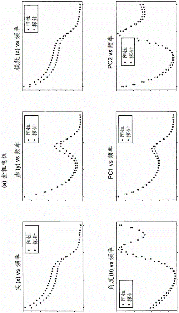
[0090] Example 1 - Studying IES Parameters for Multi-Frequency Analysis
[0091] In order to study the optimal parameters to be used in the method of the first aspect of the invention, any EIS device may be employed. However, the electrodes, electrolytes, liquid media, analytes (and probes, if used) that will be involved in the final analysis will typically be employed in order to ensure that these parameters are as close to optimum as possible.
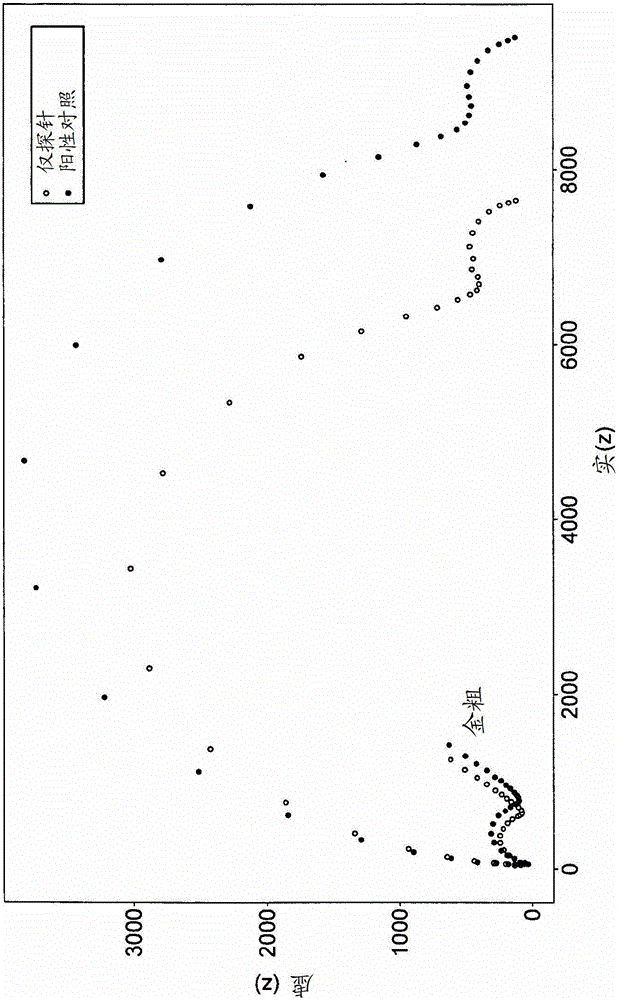
[0092] In this example, probe-target hybridization on a commercial gold IDE from Abtech was studied. Using an electrochemical cleaning cycle, two electrodes in the IDE pair were subjected to 2 SO 4 Linear potential sweep of Ag / AgCl in aqueous solution between -0.6V and +1.65V for 30-40 complete cycles at a sweep rate of 50mV until a stable cyclic voltammogram (CV) of a clean gold electrode is seen feature. Before preparing the DNA (69-merITI021) solution, the DNA probes were passed through the MicroSpin after cleavage of disulfid...
example 2
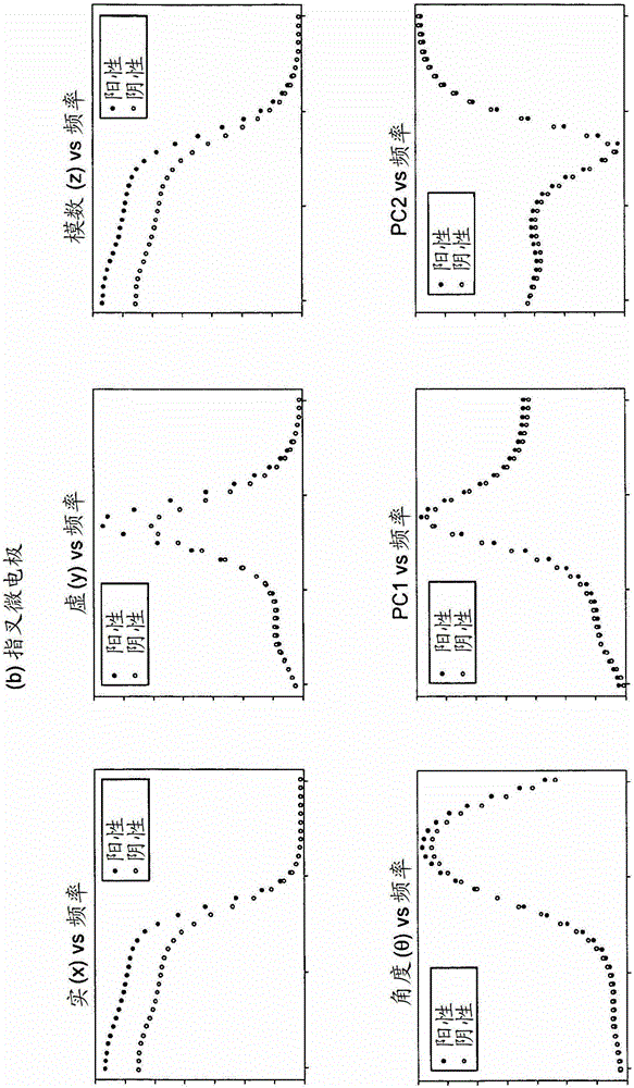
[0111] Example 2 - Studying real-time kinetic measurements using EIS
[0112] In this example, the kinetics of probe-target hybridization on a commercial gold IDE from Alberta Tech was studied. Using an electrochemical cleaning cycle, the two electrodes in the IDE pair were subjected to 2 SO 4 Linear potential sweep between -0.6V and +1.65V of Ag / AgCl in aqueous solution, 30-40 full cycles at a sweep rate of 50mV until a stable cyclic voltammogram (CV) of a clean gold electrode is seen feature. Before preparing this DNA (69-merITI021) solution, pass the DNA probe through the MicroSpin after cleavage of the disulfide-protected nucleotide with 5 mM TCEP solution TM G-25 column (Amersham Biosciences (Amersham Biosciences), Buckinghamshire, UK) was used for purification.
[0113] Immediately after cleaning, the thiol-DNA probe layer was submerged in 2xSSC buffer and (Fe(CN) 6 ) 3- with (Fe(CN) 6 ) 4- Each l0mM (10mM (Fe(CN) 6 ) 3- / 4- ) in 10 μM DNA solution. EIS measure...
PUM
 Abstract
Description
Claims
Application Information
 - Generate Ideas
- Intellectual Property
- Life Sciences
- Materials
- Tech Scout
- Unparalleled Data Quality
- Higher Quality Content
- 60% Fewer Hallucinations
Browse by: Latest US Patents, China's latest patents, Technical Efficacy Thesaurus, Application Domain, Technology Topic, Popular Technical Reports.
© 2025 PatSnap. All rights reserved.Legal|Privacy policy|Modern Slavery Act Transparency Statement|Sitemap|About US| Contact US: help@patsnap.com