Eureka AIR delivers breakthrough ideas for toughest innovation challenges, trusted by R&D personnel around the world.

Method, brace and system for measuring torsion or bending of a part of a human or animal body

A technology for detecting devices and limbs, applied in the field of brackets measuring torsion or bending, and systems for measuring torsion or bending, which can solve problems such as performance degradation, mechanical damage, and fiber fragility

Active Publication Date: 2012-10-24
NEDERLANDSE ORG VOOR TOEGEPAST-NATUURWETENSCHAPPELIJK ONDERZOEK (TNO)
View PDF4 Cites 5 Cited by
  • Summary
  • Abstract
  • Description
  • Claims
  • Application Information

AI Technical Summary

Problems solved by technology

[0007] The problem with using fiber optics to measure angles is that the maximum angle of bend is limited to about 30 degrees due to possible breakage at larger angles and due to possible light transmission only at smaller angles
Moreover, such fibers are fragile and susceptible to mechanical damage, such as the so-called cladding, resulting in less precision, reduced performance and especially reduced reliability

Method used


Image

  • Method, brace and system for measuring torsion or bending of a part of a human or animal body
  • Method, brace and system for measuring torsion or bending of a part of a human or animal body
  • Method, brace and system for measuring torsion or bending of a part of a human or animal body

Examples


example

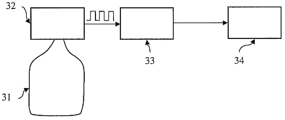
[0053] exist image 3 In the embodiment of the method shown in , the conductive loop is a 30 cm by 10 cm rectangular coil with a single winding made of metal wire, with one end open for two joints, used to measure inductance. Use a 2.5MHz oscillator to measure the inductance of this loop. This oscillator has a series of pulses that represent the frequency of the inductive based sensor. The inductive sensor is connected in series with the second coil Ls=470nH and capacitor C=5.7nF. A calculator is used to calculate the oscillator's pulse as 10ms. Assume the N measurement is calculated as 10ms. Then, the frequency is measured as

[0054] fm=N*100in Hz

[0055] Then, use

[0056] 2*pi*fm=1 / sqrt(L*C) or

[0057] Lm=1 / (C*(2*i*fm)^2)

[0058] Calculate the inductance.

[0059] Therefore, the actual bend sensor inductance is

[0060] L =Lm-Ls

[0061] Typical values ​​for the inductance L of this loop are between 400 and 600 nH. Figure 7The relationship between the bendi...


PUM


Abstract

Method, brace (55), and system for measuring a degree of torsion or bending of a part of a human or animal body. The method comprises the steps of attaching a sensor (56) to a part of the human or animal body, obtaining calibration data of the sensor by detecting the output signal of the sensor for a well defined degree of torsion or bending of said part of the human or animal body, storing the calibration data, measuring an output signal of the sensor during torsion or bending of said part of the human or animal body, and a final step of relating said output signal of the sensor to a degree of torsion or bending by using the calibration data. The method, brace and system are characterised in that the sensor comprises an electrically conductive loop (51), the area of said loop at least partially covering said part of the human or animal body, for instance a knee, and that the sensor further comprises an output unit (57) for providing an output signal that is a measure for the inductance of the loop.

Description

technical field [0001] The present invention relates to a method for measuring twisting or bending at a joint between two limbs, such as a part of a human or animal body. The invention also relates to a system for measuring twist or bend. Furthermore, the invention also relates to a stand for measuring twist or bend. Background technique [0002] Measuring twisting or bending of parts of the human or animal body, such as the knee or neck, is important for science or therapy. The information obtained from such measurements can be used to improve human or animal capabilities, such as in sports, and to prevent strain injuries. [0003] Ravindra Wijesiriwardana's article entitled "Inductice Fiber-Meshed Strain and Displacement Transducers for Respiratory Measuring Systems and Motion Capturing Systems" published in IEEE Sensors Journal Vol. 6, No. 3 (kune 2006), pp. 571-579 describes the body Motion sensor (EPO reference number XP-002580465). The article proposes the use of c...

Claims


Application Information

Patent Timeline
IPC IPC(8): A61B5/103A61B5/053
CPCA61B5/11A61B2505/09A61B2503/10A61B5/45A61B5/1071A61B5/1122A61B5/6828A61B5/4528A61B5/1121
Inventor 帕拉斯克瓦斯·杜尼亚斯安德鲁·斯塔塔姆赫拉尔杜斯·约翰尼斯·尼古拉斯·杜德曼靳安民
Owner NEDERLANDSE ORG VOOR TOEGEPAST-NATUURWETENSCHAPPELIJK ONDERZOEK (TNO)
Why Eureka
Eureka Blog
Learn More