Shield connector

一种连接器、电连接的技术,应用在连接、导电连接、连接装置的零部件等方向,能够解决屏蔽导体风雨侵蚀等问题

Inactive Publication Date: 2012-10-24
SUMITOMO WIRING SYST LTD
View PDF8 Cites 19 Cited by
  • Summary
  • Abstract
  • Description
  • Claims
  • Application Information

AI Technical Summary

Problems solved by technology

[0004] Shielded conductors used outside the vehicle may be exposed to wind and rain, and water may penetrate into the shielded case through the gap between the housing and the shielded case

Method used


Image

  • Shield connector
  • Shield connector
  • Shield connector

Examples


Embodiment Construction

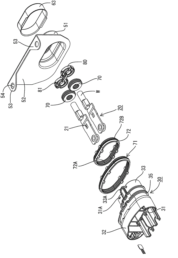
[0014] exist Figure 4 , the shielded connector according to the invention is indicated by reference 10 and can be mounted in a mounting hole C1 in a metal case C containing the device.

[0015] Such as figure 1 As shown, the shielded connector 10 includes a housing 30 made of synthetic resin. The terminal fittings 20 connected to the ends of the electric wires W are accommodated in the case 30 , and the shield case 50 covers the case 30 .

[0016] Each terminal fitting 20 is a flat plate, and the wire W is electrically connected to the rear portion of the terminal fitting 20, such as figure 2 with Figure 5 shown. Further, the locking hole 21 vertically penetrates a substantially central portion of the terminal fitting 20 in the front-rear direction.

[0017] The housing 30 is a hollow wide flat tube in the front-to-back direction, such as figure 2 shown. The front end of the housing 30 has a large oval housing portion 32 and the rear end of the housing 30 has a smal...


PUM


Abstract

A shield connector (10) is mounted in a metal case (C) that contains a device to be mounted in a vehicle. The shield connector (10) has a housing (30) in which terminal fittings (20) connected to ends of wires (W) are accommodated and from which the wires (W) are pulled out. Rubber plugs (70) are provided for sealing between the inner peripheries of cavities (31) in the housing (30) and the outer peripheries of the wires (W). A shield shell (50) covers the housing (30) and is connected electrically to the case (C) and also to a shield conductor (60) through which the wires (W) are inserted. A second rubber ring is provided between the housing (30) and the shield shell (50).

Description

technical field [0001] The invention relates to a shielded connector. Background technique [0002] US Patent No. 7934950 discloses a shielded connector to be connected with a device installed in a vehicle. The device is arranged in a metal casing, and the shielded connector is mounted to the metal casing. The shielded connector includes a housing for holding terminal fittings connected to electric wires. The wires are pulled from the housing, and the rubber seal provides a seal between the outer perimeter of the wires and the inner perimeter of the housing. A tubular shielding shell is mounted on the housing to cover the outer surface of the housing. [0003] The shielding case is electrically connected to the case, and a shielding conductor such as a braided wire covers the wires drawn from the case to provide shielding from the case to the shielding conductor. [0004] Shielded conductors used outside the vehicle may be subject to wind and rain erosion, and water may ...

Claims


Application Information

Patent Timeline
Patent Type & Authority Applications(China)
IPC IPC(8): H01R13/52H01R13/648H01R13/516
CPCH01R13/748H01R13/5205H01R13/5202H01R9/032H01R13/65912
Inventor 河村政幸
Owner SUMITOMO WIRING SYST LTD
Why Eureka
Try Eureka