
Multi-beam antenna array and multi-beam antenna

A multi-beam antenna and antenna sub-array technology, which is applied in the direction of antenna array, antenna, radiation element structure, etc., can solve the problem of unsatisfactory side lobe level in the horizontal plane, and achieve the effect of optimizing the side lobe level

Active Publication Date: 2012-10-24
HUAWEI TECH CO LTD
View PDF4 Cites 20 Cited by
  • Summary
  • Abstract
  • Description
  • Claims
  • Application Information

AI Technical Summary

Problems solved by technology

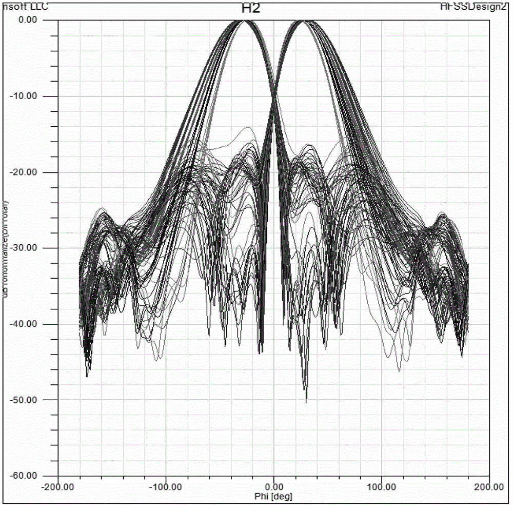
[0003] In the prior art, the antenna array using square grid arrangement has the problem of unsatisfactory sidelobe level in the horizontal plane

Method used


Image

  • Multi-beam antenna array and multi-beam antenna
  • Multi-beam antenna array and multi-beam antenna
  • Multi-beam antenna array and multi-beam antenna

Examples


Embodiment Construction

[0027] In the embodiment of the present application, the multi-beam antenna array provided mainly designs two different antenna sub-arrays in the multi-beam antenna array, wherein the multi-beam antenna array includes at least one first antenna sub-array and at least one second antenna In the sub-array, the first antenna sub-array includes a plurality of first radiating units arranged in a square grid, and the second antenna sub-array includes a plurality of second radiating units arranged in a triangular grid . If the multi-beam antenna array only uses the first antenna sub-array, the first side lobe level of the antenna is low and the second side-lobe level is high; if the multi-beam antenna array uses the second antenna sub-array alone, its horizontal plane The first sidelobe level is high and the second sidelobe level is low. Through the mixing of two antenna sub-arrays, the horizontal plane sidelobe level value of the multi-beam antenna array takes the average value of t...


PUM


Abstract

The invention discloses a multi-beam antenna array and a multi-beam antenna. The multi-beam antenna array comprises at least one first antenna sub-array and at least one second antenna sub-array, wherein the first antenna sub-array comprises a plurality of first radiation units which are arrayed in a square grid way; and the second antenna sub-array comprises a plurality of second radiation units which are arrayed in a triangular grid way. The first antenna sub-array arrayed in the square grid way and the second antenna sub-array arrayed in the triangular grid way are mixed in the same multi-beam antenna array, so that the index of the sidelobe level of the horizontal plane of the multi-beam antenna can be effectively optimized.

Description

technical field [0001] The present application relates to antenna technology, in particular to a multi-beam antenna array and a multi-beam antenna. Background technique [0002] With the development of mobile communication, users have higher and higher requirements for the capacity of the communication system; an effective way to improve the system capacity is to use multi-beam antennas for antennas. Generally speaking, multi-beam antennas usually include beamforming networks and The antenna array connected to the network, beamforming network, a typical application structure is a Butler matrix. The radiating elements in the antenna array are arranged in a square grid, that is, they are not arranged in parallel. [0003] Antenna arrays arranged in a square grid in the prior art have the problem of unsatisfactory sidelobe levels in the horizontal plane. Contents of the invention [0004] The invention provides a multi-beam antenna array and a multi-beam antenna to optimize...

Claims


Application Information

Patent Timeline
Patent Type & Authority Applications(China)
IPC IPC(8): H01Q21/00H01Q1/36
Inventor 艾鸣
Owner HUAWEI TECH CO LTD
Learn More