
Method and device for tracking sun by solar panel

A technology of solar panels and the sun, which is applied in the field of solar panels tracking the sun, can solve the problems of harsh installation environment, changes in measurement accuracy, and inability to achieve the effect of tracking light, and achieve the effect of good economy and low price

Inactive Publication Date: 2012-10-24
CENT SOUTH UNIV
View PDF5 Cites 6 Cited by
  • Summary
  • Abstract
  • Description
  • Claims
  • Application Information

AI Technical Summary

Problems solved by technology

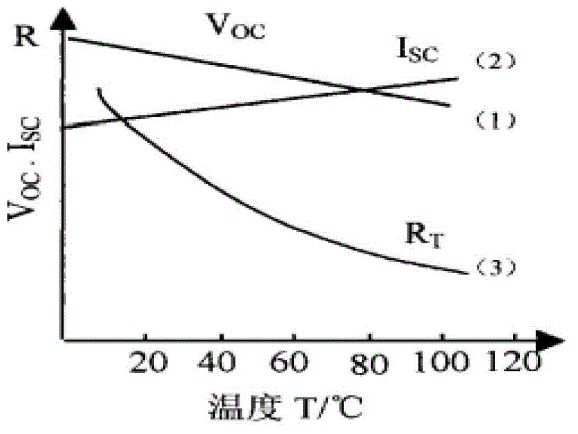
[0006] 1. Due to the functional limitations of the solar tracker, its installation environment is relatively harsh, and it needs to withstand the variable outdoor temperature, wind, frost, rain and snow. The traditional light intensity sensor is relatively simple and only has the sensor function. When the temperature changes, the measurement accuracy will change. a big change
[0007] 2. The light-following strategy of the traditional solar tracker is relatively simple. It just gives a deflection angle or light-sensitive position by feeling. Therefore, the best light-following effect cannot be achieved.
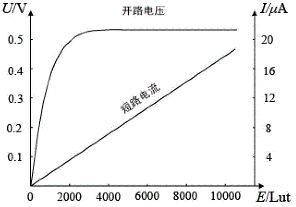
[0008] 3. The light sensor used in the traditional solar tracker does not have a linear relationship with the light intensity, but only an approximate linear relationship, so it has a great impact on the measurement results

Method used


Image

  • Method and device for tracking sun by solar panel
  • Method and device for tracking sun by solar panel
  • Method and device for tracking sun by solar panel

Examples


Embodiment 1

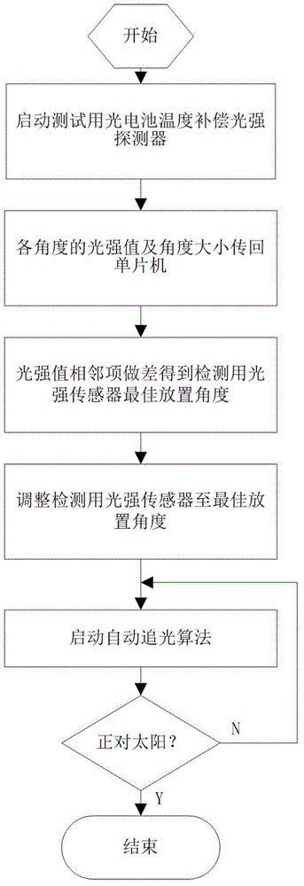
[0063] The flow chart of the whole method is as follows figure 1 As shown, the system is installed on the upper part of an outdoor parking lot steel frame as an example to illustrate the actual operation effect of the present invention:

[0064] The parking lot is mainly for small cars, the size of the parking space is 2600mm×5200mm, and the width of the vehicle aisle is 5600mm. The height of the steel frame structure is 3000mm, the unit cell is 8600mm long and 8000mm wide, see Figure 7 . Each tracking unit is equipped with three photovoltaic panels, with a total size of 1240mm×2540mm, referred to as Tracker. The design requires that the central axis be in a north-south direction, and the steel frame structure on the lower floor may not be able to meet the north-south direction due to objective constraints, so the supporting structure of the designed light tracking system can be independent from the next steel frame. In order to avoid mutual occlusion of each Tracker, the...


PUM


Abstract

The invention discloses a method and a device for tracking the sun by a solar panel. The method comprises the following steps of: 1) determining an optimal placing dip angle of a light intensity sensor used for testing, arraning the light intensity sensor on a test plate, rotating the light intensity sensor used for testing for 180 degrees in an east-west vertical plane or a south-north vertical plane by starting from the fact that the test plate is vertical to the ground plane on the test plate, recording a light intensity value and a corresponding angle value in the rotating process, making a difference between the light intensity values of adjacent items to obtain a point with the maximum difference value, taking the point as a jump point of the light intensity, taking an angle corresponding to the jump point as an optimal placing dip angle of the light intensity sensor used for testing, and according to the optimal placing dip angle, fixing the light intensity sensor used for testing; and 2) on the basis of the light intensity sensor used for testing, which is arranged on a surface plate, executing an automatic light following step, and regulating the dip angle of the surface plate to enable the surface plate to track the sun in real time. The method and the device for tracking the sun by the solar panel have the advantages of high precision and easiness in implementation.

Description

technical field [0001] The invention belongs to the technical field of electronic information, and relates to a method and a device for tracking the sun by a solar panel. Background technique [0002] Human beings' exploitation of natural energy has entered a new period from the past exploitation of oil and coal, that is, a new energy period dominated by renewable energy such as solar energy and wind energy. Developed countries such as the West and Japan have popularized solar power generation in their countries, but the efficiency of collecting solar energy with fixed panels needs to be improved. Therefore, it is imperative to invent an efficient and stable solar panel light tracking device. [0003] As we all know, most of the current solar panels are fixed in one direction, so the utilization rate of solar energy is low. At present, some people have designed a solar tracker, but the design is complex, the anti-interference is poor, and there is no strict scientific argum...

Claims


Application Information

Patent Timeline
IPC IPC(8): G05D3/12
Inventor 杨小冬安剑奇吴敏施陈俊陈桂彬
Owner CENT SOUTH UNIV
Learn More