
Horizontal underwater manual ventilation cavitation simulating device

A cavitation and artificial technology, applied in the direction of weapon accessories, ammunition testing, ammunition, etc., to achieve the effect of simple design and ingenious structure

Inactive Publication Date: 2012-10-24
INST OF MECHANICS - CHINESE ACAD OF SCI
View PDF7 Cites 8 Cited by
  • Summary
  • Abstract
  • Description
  • Claims
  • Application Information

AI Technical Summary

Problems solved by technology

However, people's research on the influence of cavitation pressure and the changing law of cavitation cycle is still in its infancy, and more in-depth experimental and theoretical research is needed.

Method used


Image

  • Horizontal underwater manual ventilation cavitation simulating device
  • Horizontal underwater manual ventilation cavitation simulating device

Examples


Embodiment Construction

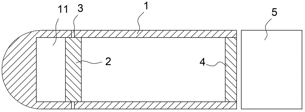
[0013] Such as figure 1 As shown, a simulated underwater artificial ventilation cavitation device of the present invention includes: an elastic body 1 and a sealed piston 2. The elastic body 1 has a cavity 11 with a predetermined volume, and a plurality of vent holes 3 are opened on the elastic body 1 . The sealing piston 2 is movably arranged in the cavity 11 of the elastic body 1 and is located at the position where the vent 3 is opened. The sealing piston 2 and the elastic body 1 form a closed fit to ensure that the elastic body 1 is placed under water. When the sealing piston 2 is at the position of the vent 3, the water outside the elastic body 1 can be prevented from entering the cavity 11.

[0014] In the embodiment of the present invention, the cavity 1 is divided into two parts by the sealed piston 2, and the two parts have substantially the same air pressure. The elastic body 1 is a cylindrical shell with an open end, and a rear cover 4 is detachably installed at the o...


PUM


Abstract

The invention discloses a horizontal underwater manual ventilation cavitation simulating device, which comprises a projectile body and a sealing piston. The projectile body has a cavity with preset volume. A plurality of ventilation holes are arranged in the projectile body. The sealing piston is movably arranged in the cavity of the projectile body and is arranged at positions where the ventilation holes are arranged. The sealing piston and the projectile body are in closed fit with each other. By simulating the momentum transmission rod of an underground launching device, when the projectile body is launched, the projectile body is instantly accelerated to a high-speed state, the sealing piston cannot move immediately under the effect of inertia, the sealing piston and the projectile body move relatively and the cavity is communicated with the external world through the ventilation holes. In the high-speed moving process of the projectile body, the pressure of the area of the ventilation holes is much smaller than normal pressure in the cavity, air runs out of the ventilation holes at the moment to form a manual ventilation cavitation phenomenon.

Description

Technical field [0001] The invention relates to a simulated horizontal underwater artificial ventilation cavitation device. Background technique [0002] When the speed of an underwater object reaches a certain critical condition, the pressure around the local area of ​​the object will be lower than the saturated vapor pressure, and the nearby water body will vaporize, forming cavitation. Cavitation is common in many high-speed underwater movements such as propellers, submarines, and torpedoes. Local cavitation will cause irregular changes in the pressure around the object, which will seriously affect the trajectory of high-speed objects such as submarines and torpedoes. [0003] However, cavitation also has a good side. It will reduce the water resistance in the cavitation area. People use this to establish artificial ventilation cavitation technology to increase the cavitation phenomenon around moving objects and even achieve supercavitation. The purpose of resistance reduction...

Claims


Application Information

Patent Timeline
IPC IPC(8): F42B35/00
Inventor 魏延鹏王一伟杜特专吴先前黄晨光廖丽娟王曦宋宏伟
Owner INST OF MECHANICS - CHINESE ACAD OF SCI
Learn More