
Identification method of vehicle current driving road condition based on shock absorber damping analytical simulation

A technology of driving road condition and identification method, applied in the field of road condition identification, can solve the problems of lack of simple and feasible road condition identification technology, no reliable driving road condition identification model, high cost, etc., and achieve lower price, fewer sensors, and simple identification method Effect

Inactive Publication Date: 2014-10-08
SHANDONG UNIV OF TECH
View PDF4 Cites 0 Cited by
  • Summary
  • Abstract
  • Description
  • Claims
  • Application Information

AI Technical Summary

Problems solved by technology

[0002] Although some domestic and foreign studies have been carried out on the identification of vehicle driving conditions, due to the constraints of the key technology of real-time simulation of shock absorber characteristics, most of them use image sensing equipment and analysis instruments to analyze and predict the driving conditions, which is costly. Difficult to promote, only installed and used on a few high-end cars
The main problem is that there is no reliable driving road condition identification model, and there is a lack of simple and feasible road condition identification technology.

Method used


Image

  • Identification method of vehicle current driving road condition based on shock absorber damping analytical simulation
  • Identification method of vehicle current driving road condition based on shock absorber damping analytical simulation
  • Identification method of vehicle current driving road condition based on shock absorber damping analytical simulation

Examples


Embodiment Construction

[0015] The present invention will be further described in detail below in conjunction with the drawings and embodiments.

[0016] Single wheel sprung mass of a suspension system of an off-road vehicle m 2 =400kg; unsprung mass m 1 =40kg; Suspension spring stiffness K=29679N / m and tire stiffness K t = 260000N / m; natural frequency f of the body 0 =1.35Hz; according to the structure, valve system parameters and oil parameters of the controllable double-tube hydraulic shock absorber, including: shock absorber installation lever ratio i=0.8; shock absorber installation angle β=15°; piston rod Diameter d=20mm; Piston cylinder diameter D=28mm; Normally through orifice area A 0 =0.2mm 2 ; Piston hole number n h =4; piston hole diameter d h =2.0mm; Piston hole length L h =10mm; the gap between the piston and the cylinder δ H =0.04mm; oil density ρ=890kg / m 3 ; Dynamic viscosity μ t = 8900kg / ms; adjustable orifice radius r = 1.0mm; rotating shaft outer radius R = 6.0mm; helix angle α = 30°.

...


PUM


Abstract

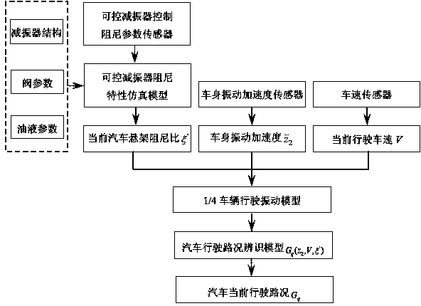
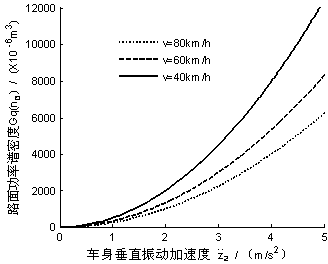
The invention relates to a method for identifying a current driving road condition for an automobile on the basis of analytical simulation of damping of a shock absorber, and belongs to the field of identification of road conditions. The method includes building a simulation model of damping characteristics of the shock absorber according to the structure of the controllable shock absorber, parameters of a valve and parameters of oil; obtaining a current damping ratio of a suspension system of the automobile by the aid of control parameter feedback signals of the controllable shock absorber via the simulation model of the damping characteristics of the controllable shock absorber; acquiring vibration acceleration of an automobile body by an acceleration sensor and acquiring the current driving speed by a speed sensor; and building a driving road condition identifying model according to a 1 / 4 automobile driving vibration model by the aid of relation among current parameters and the damping ratio of the suspension system, the vibration acceleration of the automobile body, the speed and road conditions, and obtaining the current driving road condition for the automobile via the driving road condition identifying model. The method for identifying the current driving road condition for the automobile is simple, convenient and reliable, the quantity of the adopted sensors is low, and the method can be used for identifying road conditions for semi-automatic suspension systems.

Description

Technical field [0001] The invention relates to a road condition identification method, in particular to the identification technology of the current road condition of a car. Background technique [0002] Although domestic and foreign researches have been conducted on vehicle driving road condition identification, due to the constraints of the key technology of real-time simulation of shock absorber characteristics, most of them use image sensing equipment and analytical instruments to analyze and predict driving road conditions, which is costly. Difficult to promote, only installed and used in a few high-end cars. The main problem is that there is no reliable road condition recognition model and the lack of simple and feasible road condition recognition technology. With the continuous improvement of people's requirements for safety and comfort, the installation of a continuous control semi-active suspension system based on driving road condition identification will become the d...

Claims


Application Information

Patent Timeline
Patent Type & Authority Patents(China)
IPC IPC(8): B60W40/06G06F17/50
CPCY02T10/82Y02T90/00
Inventor 周长城李红艳赵雷雷
Owner SHANDONG UNIV OF TECH
Learn More