Auxiliary braking system of centrifugal hydraulic light vehicle

A vehicle auxiliary and braking system technology, applied in the direction of brakes, vehicle components, brake transmission devices, etc., can solve the problems of easy heat decay, limited braking torque, short service life, etc., to achieve high system reliability, safety, The effect of mature manufacturing process and high service life

Inactive Publication Date: 2012-10-24
广东卡达克汽车科技有限公司
View PDF4 Cites 4 Cited by
  • Summary
  • Abstract
  • Description
  • Claims
  • Application Information

AI Technical Summary

Problems solved by technology

[0004] Generally, friction brakes are the most widely used in existing vehicle brake systems. Friction brakes are further divided into disc brakes and drum brakes. Friction brakes have a simple and mature structure, but they have disadvantages such as easy heat decay and wear of friction parts, so the service life Short; existing large vehicles are usually equipped with hydraulic or electromagnetic retarders to overcome the above shortcomings. The electromagnetic retarder is non-contact and has a long life, but the braking torque is limited, the structure is complicated, the automatic control requirements and the manufacturing cost are high. Difficult to promote, the current hydraulic retarder is too heavy and requires high cooling, generally equipped with large vehicles, not suitable for small and medium vehicles

Method used


Image

  • Auxiliary braking system of centrifugal hydraulic light vehicle
  • Auxiliary braking system of centrifugal hydraulic light vehicle

Examples


Embodiment Construction

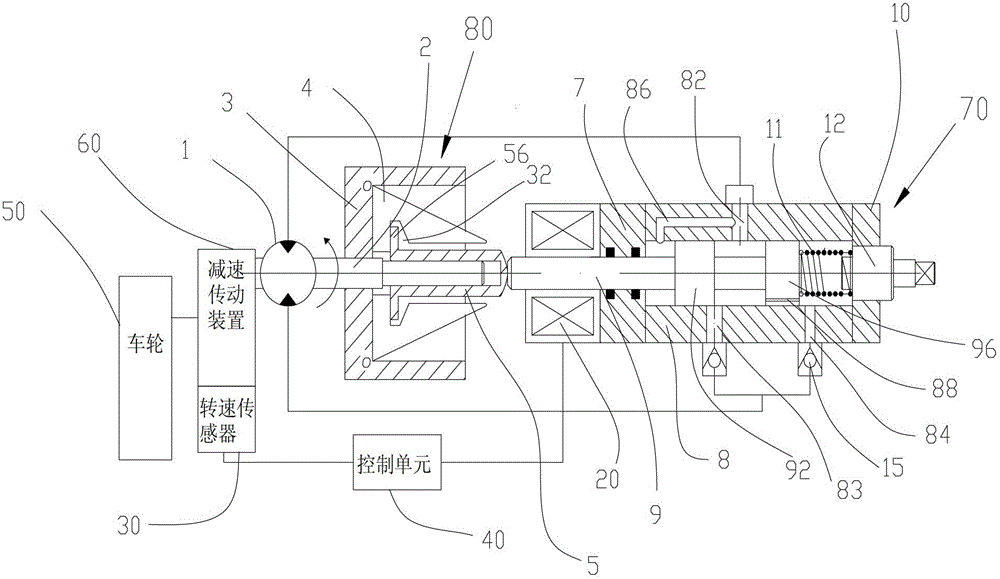
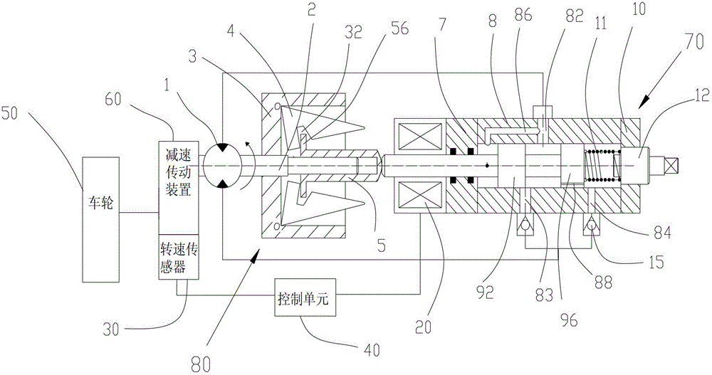
[0024] Below in conjunction with accompanying drawing and specific embodiment, the present invention will be further described:

[0025] See figure 1 , the present invention relates to a centrifugal hydraulic light vehicle auxiliary braking system, and its preferred embodiment includes a reduction transmission device 60, a rotational speed sensor 30, a hydraulic motor 1, a control unit 40, an electromagnetic coil 20, a centrifugal device 80 and a flow control valve 70. The hydraulic motor 1 is connected to the reduction transmission device 60, and the reduction transmission device 60 is connected to the wheel 50. The rotational speed sensor 30 is installed on the reduction transmission device 60 to detect the rotational speed, and is connected to the control unit 40 to send the detected rotational speed to the control unit 40 , the control unit 40 is connected with the electromagnetic coil 20 to adjust the current of the electromagnetic coil 20 according to the rotational spe...


PUM


Abstract

The invention relates to an auxiliary braking system of a centrifugal hydraulic light vehicle. The auxiliary braking system comprises a hydraulic motor, a speed reduction transmitting device, a rotation speed sensor, a control unit, a magnet coil, a centrifugation device and a flow control valve, wherein the hydraulic motor is connected with the speed reduction transmitting device, the speed reduction transmitting device is connected with wheels of the vehicle, the rotation speed sensor is arranged on the speed reduction transmitting device to detect the rotation speed, the rotation speed sensor is connected with the control unit so as to send the detected rotation speed to the control unit, and the control unit is connected with the magnet coil so as to adjust the current of the magnet coil according to the rotation speed. The magnet coil is sleeved outside a left end part of a valve core of the flow control valve. A rotary shaft of the centrifugation device is arranged on the hydraulic motor, and a sliding sleeve of the centrifugation device is close to the left end part of the valve core of the flow control valve. The auxiliary braking system of the centrifugal hydraulic light vehicle disclosed by the invention has a simple structure, the manufacturing process is mature, the cost is lower, the reliability and the safety of the system are high, and the system can be used as an auxiliary braking system of ordinary small and medium size vehicles, and has long service life.

Description

[0001] technical field [0002] The invention relates to a centrifugal hydraulic light vehicle auxiliary braking system. [0003] Background technique [0004] Generally, friction brakes are the most widely used in existing vehicle brake systems. Friction brakes are further divided into disc brakes and drum brakes. Friction brakes have a simple and mature structure, but they have disadvantages such as easy heat decay and wear of friction parts, so the service life Short; existing large vehicles are usually equipped with hydraulic or electromagnetic retarders to overcome the above shortcomings. The electromagnetic retarder is non-contact and has a long life, but the braking torque is limited, the structure is complicated, the automatic control requirements and the manufacturing cost are high. Difficult to promote, the current hydraulic retarder is too heavy and requires high cooling. It is generally equipped with large vehicles and is not suitable for small and medium vehicl...

Claims


Application Information

Patent Timeline
Patent Type & Authority Applications(China)
IPC IPC(8): B60T8/36B60T13/68
Inventor 肖启瑞石本改李百华余剑东王波群荀斌
Owner 广东卡达克汽车科技有限公司
Why Eureka
Try Eureka