Interleaved parallel three-phase pfc circuit
A circuit, three-phase technology, applied in the field of interleaved parallel three-phase PFC circuit, can solve the problems of increased input current ripple, difficult filter design, centralized heating components, etc., to reduce input current fluctuation, facilitate PCB layout and Thermal design, effect of reducing volume
- Summary
- Abstract
- Description
- Claims
- Application Information
AI Technical Summary
Problems solved by technology
Method used
Image
Examples
Embodiment 1
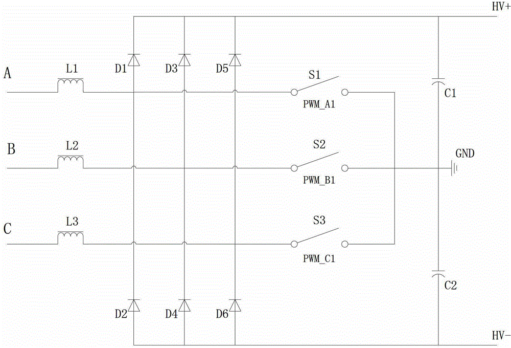
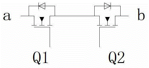
[0024] refer to Figure 1-5 , an interleaved parallel three-phase PFC circuit, which consists of two Vienna converters, the Vienna converter is a three-phase three-switch three-level PFC structure, the three-phase input of the first Vienna converter is respectively connected to the second Vienna converter Three-phase input, the three-level output of the first Vienna converter is respectively connected to the three-level output of the second Vienna converter, the first Vienna converter and the second Vienna converter each include three bidirectional switches, and the bidirectional The switches are all controlled to be turned on and off by the current magnitude of an independent inductor, the cycle start and end times of the three bidirectional switches of the first Vienna converter are the same, and the cycles of the three bidirectional switches of the second Vienna converter start Same as the end time, the cycle start and end times of the three bidirectional switches of the fi...
Embodiment 2
[0036] refer to Figure 7 The difference between this embodiment and the first embodiment is that the bidirectional switch is composed of a rectifier bridge and a switch tube, and the outputs of the rectifier bridge and the switch tube are connected in parallel. The rest of the structures and functions are the same as those in Embodiment 1.
Embodiment 3
[0038] refer to Figure 8 The difference between this embodiment and the first embodiment is that the bidirectional switch is composed of a rectifier bridge and a switch tube, and the outputs of the rectifier bridge and the switch tube are connected in parallel. Moreover, instead of connecting the middle node of the inductor and the bidirectional switch to the middle node between the two diodes in series, the two ends of the switching tube of the bidirectional switch are connected between the two diodes in series. The rest of the structures and functions are the same as those in Embodiment 1.
PUM
 Abstract
Description
Claims
Application Information
 - R&D
- Intellectual Property
- Life Sciences
- Materials
- Tech Scout
- Unparalleled Data Quality
- Higher Quality Content
- 60% Fewer Hallucinations
Browse by: Latest US Patents, China's latest patents, Technical Efficacy Thesaurus, Application Domain, Technology Topic, Popular Technical Reports.
© 2025 PatSnap. All rights reserved.Legal|Privacy policy|Modern Slavery Act Transparency Statement|Sitemap|About US| Contact US: help@patsnap.com


