
Interleaved parallel three-phase power factor correction circuit

A three-phase, parallel technology, applied in the direction of electrical components, high-efficiency power electronic conversion, sustainable manufacturing/processing, etc., can solve problems such as increased input current ripple, difficult filter design, and larger power supply volume, and achieves input Reduce current fluctuations, facilitate PCB layout and thermal design, and reduce interference

Active Publication Date: 2012-10-17
HANGZHOU ZHONGHEN ELECTRIC CO LTD
View PDF7 Cites 21 Cited by
  • Summary
  • Abstract
  • Description
  • Claims
  • Application Information

AI Technical Summary

Problems solved by technology

These two traditional methods will bring the disadvantages of increased input current ripple, difficult filter design, difficulty in thermal design due to the concentration of heat-generating devices, and larger power supply volume.

Method used


Image

  • Interleaved parallel three-phase power factor correction circuit
  • Interleaved parallel three-phase power factor correction circuit
  • Interleaved parallel three-phase power factor correction circuit

Examples


Embodiment 1

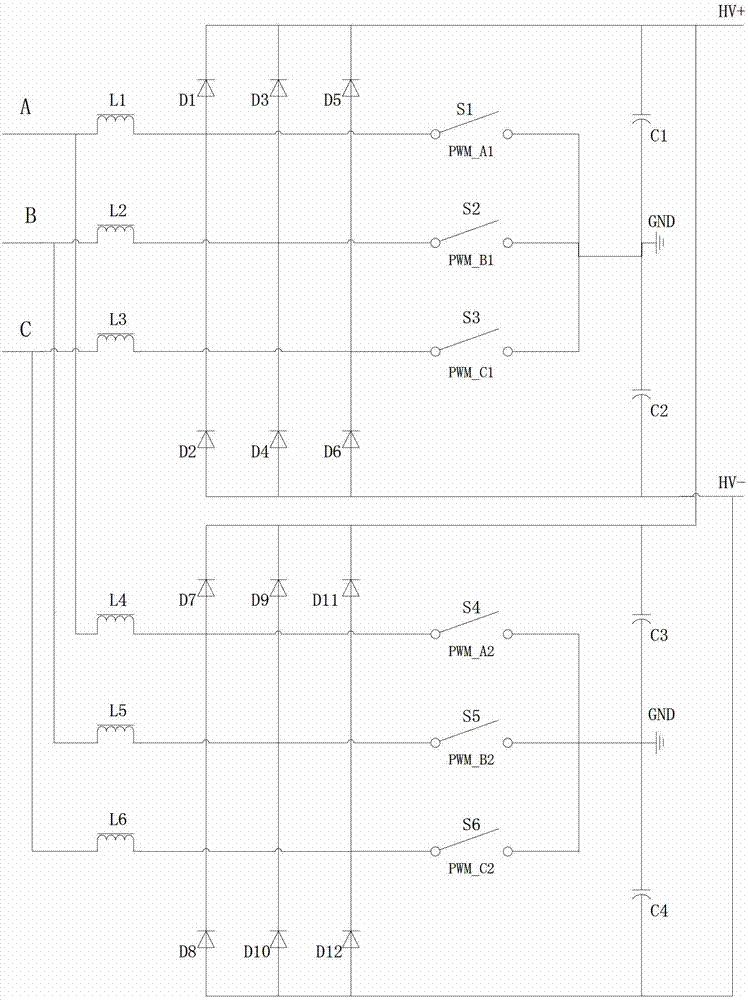
[0024] Reference Figure 1-5 , Interleaved parallel three-phase PFC circuit, which consists of two Vienna converters, the Vienna converter is a three-phase three-switch three-level PFC structure, the three-phase input of the first Vienna converter is connected to the second Vienna converter Three-phase input, the three-level output of the first Vienna converter is respectively connected to the three-level output of the second Vienna converter. Both the first Vienna converter and the second Vienna converter include three bidirectional switches. The switches are all turned on and off by the current of an independent inductor. The cycle start and end times of the three bidirectional switches of the first Vienna converter are the same, and the cycle of the three bidirectional switches of the second Vienna converter starts Same as the end time, the cycle start and end time of the three bidirectional switches of the first Vienna converter lead or lag the cycle start and end time of t...

Embodiment 2

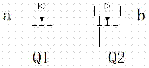
[0036] Reference Figure 7 The difference between this embodiment and the first embodiment is that the bidirectional switch is composed of a rectifier bridge and a switch tube, and the output of the rectifier bridge and the switch tube are connected in parallel. The rest of the structure and function are the same as the first embodiment.

Embodiment 3

[0038] Reference Figure 8 The difference between this embodiment and the first embodiment is that the bidirectional switch is composed of a rectifier bridge and a switch tube, and the output of the rectifier bridge and the switch tube are connected in parallel. And instead of connecting the intermediate node of the inductor and the bidirectional switch to the intermediate node between the two diodes in series, the two ends of the switch tube of the bidirectional switch are connected between the two diodes in series. The rest of the structure and function are the same as the first embodiment.


PUM


Abstract

The invention discloses an interleaved parallel three-phase power factor correction (PFC) circuit. The circuit consists of two Vienna converters, wherein the Vienna converters have three-phase three-switch three-level PFC structures; three phase inputs of the first Vienna converter are connected with three phase inputs of the second Vienna converter respectively; three level outputs of the first Vienna converter are connected with three level outputs of the second Vienna converter respectively; the period starting time and the period ending time of three bidirectional switches of the first Vienna converter are the same; the period starting time and the period ending time of three bidirectional switches of the second Vienna converter are the same; and the period starting time and the period ending time of the three bidirectional switches of the first Vienna converter are half period earlier or later than the period starting time and the period ending time of the three bidirectional switches of the second Vienna converter.

Description

Technical field [0001] The invention relates to an interleaved parallel three-phase PFC circuit. Background technique [0002] Today, when the concept of green energy is deeply rooted in the hearts of the people, power factor correction has become an indispensable part of the power supply. The application of single-phase power factor correction technology has been very mature, and single-phase PFC power supplies of 100W-4000W have been commercialized. With the increasing requirements of modern power supply systems for three-phase AC input devices that pollute the power grid, it will be an inevitable trend for high-power rectifier power supplies to adopt three-phase PFC technology. There are two ways to increase power in the traditional sense: One is to keep the number of devices unchanged and increase the device capacity. That is, the voltage and current stress of the power tube increases, and the capacity and volume of the inductor and capacitor increase; the second is simple ...

Claims


Application Information

Patent Timeline
IPC IPC(8): H02M1/42H02M1/44H02M1/12
CPCY02B70/126Y02B70/10Y02P80/10
Inventor 孙涛郭卫农
Owner HANGZHOU ZHONGHEN ELECTRIC CO LTD
Learn More