Blood gas analyzer and using method thereof

A blood gas analyzer and pump body technology, applied in the field of blood gas analyzers, can solve the problems of fragile solenoid valves, cumbersome use process, and large gas cylinders, so as to reduce the probability of failure, reduce the probability of failure, and improve reliability Effect

Active Publication Date: 2013-08-14
SHENZHEN CORNLEY BIO MEDICAL CO LTD +1
View PDF11 Cites 0 Cited by
  • Summary
  • Abstract
  • Description
  • Claims
  • Application Information

AI Technical Summary

Problems solved by technology

In this calibration method, the flow path is divided into gas path and liquid path, and the control of the gas-liquid intersection is more complicated. Especially in the case of a failure, the calibration liquid or cleaning liquid enters the gas path and easily damages the solenoid valve. In addition, Due to the existence of gas cylinders, the instrument is not convenient to be portable or hand-push, which makes the standard gas transportation inconvenient; because the standard gas is compressed gas, and the gas cylinder is large, it is not easy to transport and use, and the compressed gas has to go through It can only be used after decompression, heat preservation, and humidification, and the use process is relatively cumbersome

Method used


Image

  • Blood gas analyzer and using method thereof
  • Blood gas analyzer and using method thereof
  • Blood gas analyzer and using method thereof

Examples


Embodiment 1

[0025] Example 1, see figure 1 , A blood gas analyzer, comprising: a needle valve 101 placed in the sampling rack 1, a sample box connected to the needle valve 101, a first pump body 4 connected to the sample box 2, and a first pump connected to the first pump The waste liquid bag 7 of the body 4, the liquid detector 18 connected to the needle valve 101 and the second pump body 5, the fourth reagent bag 10 of the second pump body 5 connected through the second solenoid valve 9, and the The third solenoid valve 11 of the liquid detector 18, the first solenoid valve 8 connected to the second pump body 5, the first reagent bag 17 connected to the liquid detector 18 through the sixth solenoid valve 16, and the fifth solenoid valve 14 The second reagent bag 15 connected to the liquid detector 18, the third reagent bag 13 connected to the liquid detector 18 through the fourth solenoid valve 12, and the third pump body 6 connected to the needle valve 101 and the waste liquid bag 7 ; I...

Embodiment 2

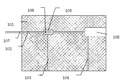
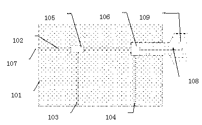
[0027] Example 2, see figure 2 , The needle valve 101 has a main channel 102, the main channel 102 has a first sampling port 105 and a second sampling port 106, the first sampling port 105 is connected to the first channel 103, and the second sampling port 106 is connected to the second Channel 104; the first reagent, the second reagent, the deproteinized solution, and the cleaning solution enter the main channel 102 in the needle valve 101 through the first channel 103, and enter the subsequent flow tube 3 at the first sampling port 105 of the main channel 102; When cleaning the flow path, the cleaning fluid entering the main channel 102 is divided into two parts. One part enters the flow path tube 3 from the first sampling port 105, cleans the sample box 2 and subsequent flow paths, and finally enters the waste fluid bag 7, and the other part The second sampling port 106 enters the second channel 104, is drawn out by the third pump body 6, and finally enters the waste liquid ...

Embodiment 3

[0028] Example 3, see figure 1 with figure 2 , The first channel 103 is connected to the liquid detector 18, so that the first reagent, the second reagent, the deproteinized solution, and the cleaning solution enter the main channel 102 in the needle valve 101 through the flow pipe 3, and the second channel 104 passes through the flow path The tube 3 is connected to the third pump body 6, so that the cleaning fluid can smoothly pass through the third pump body 6 and enter the waste fluid bag 7, thereby facilitating cleaning of the flow path.


PUM


Abstract

Disclosed is a blood gas analyzer, comprising a needle valve (101) situated in a sampling frame, a sample box (2) connected to the needle valve, a first pump body (4) connected to the sample box, a waste liquid bag (7) connected to the first pump body, a liquid detector (18) connected to the needle valve and a second pump body (5), a third electromagnetic valve (11) connected to the liquid detector, a first electromagnetic valve (8) connected to the second pump body, and a third pump body (6) connected to the needle valve and the waste liquid bag, wherein in the sample box, one end of a front detector (201) is connected to the needle valve and the other end is successively connected to a detection membrane tube (202) and a rear detector (203), and the rear detector is connected to the first pump body; the preceding components are connected to each other through flow tubes (3); a memory device (205) is connected to the detection membrane tube via electrodes (204); and both the first electromagnetic valve (8) and a second electromagnetic valve (9) are provided with air inlets. By means of the calibration of a liquid instead of the prior art method of mixed calibration of a gas and liquid, faults caused by the liquid entering an air path can be avoided, and the reliability of the instrument is improved.

Description

Technical field [0001] The invention relates to the field of medical testing, in particular to a blood gas analyzer and a method of use thereof. Background technique [0002] The PCO2 and PO2 electrodes of the existing domestic blood gas analyzers are calibrated using high-gas and low-gas two compressed gases with different gas ratios. After decompression, heat preservation, and humidification, they are introduced into the electrode measurement channel for calibration, and the remaining electrodes use standard liquids. target. In this calibration method, the flow path is divided into the gas path and the liquid path, and the control of the gas-liquid intersection is more complicated. Especially in the case of failure, the calibration fluid or cleaning fluid entering the gas path can easily damage the solenoid valve. In addition, Due to the existence of gas cylinders, it is not convenient for the instrument to be made into a portable or hand-push type that can be used, which make...

Claims


Application Information

Patent Timeline
Patent Type & Authority Patents(China)
IPC IPC(8): G01N33/48
CPCG01N33/4925G01N35/00G01N33/48A61B5/145A61B5/14G01N35/1095
Inventor 侯兴凯姚新宁
Owner SHENZHEN CORNLEY BIO MEDICAL CO LTD
Why Eureka
Try Eureka